
Device for smoking tobacco and other inhalation materials

a tobacco and inhalation device technology, applied in the field of vaporizers/inhalators, can solve the problems of no self-contained electronic smoking devices that incinerate matter into ash and smoke, temperature of smoke, unpleasant burning sensation and sometimes coughing, etc., and achieve the effect of reducing the need for restrictive airflow and increasing the smoking

Active Publication Date: 2021-11-11
YANKELEVICH DMITRY
View PDF5 Cites 0 Cited by
  • Summary
  • Abstract
  • Description
  • Claims
  • Application Information

AI Technical Summary

Benefits of technology

The present invention is a smoking apparatus that cools hot smoke to the body temperature, allowing more smoke to be inhaled and held in the lungs for a longer period of time, increasing the smoking effect. The invention also eliminates the need for restrictive airflow. Additionally, the invention offers a vaporizer / inhalation device that maximizes pressure drop while intensifying heat exchange, allowing for a wide range of heating methods. This device can vaporize content at lower, middle, or higher temperatures, providing flexibility in the vaporization process.

Problems solved by technology

The difficulty of creating the balance between the natural ability of human lungs to create the pressure drop and desired dosage of smoke intake while inhaling has always been the biggest problem of smoking.
However, there are no self-contained electronic smoking devices that incinerate matter into ash and smoke.
The main factor that is causing just said problem is the temperature of the smoke.
Delivery of hot gases into the lungs does not only cause a very unpleasant burning sensation and sometimes coughing, but also, according to the majority of modern medical studies, is the main cause of destructive effect that smoking imposes to the human's mouth and lungs.
Therefore, the problem of decreasing of the temperature of the hot smoke right at the moment of smoking is the very important goal and the technical challenge.
This is a problem for many former and current smokers of cigarettes and tobacco pipes.
Furthermore, some people prefer not to use external heating sources, which may be difficult to aim and even operate in turbulent conditions and are flat out dangerous.
All other electronic self-contained smoking devices and e-cig vaporizers are not designed to incinerate plant matter thus they are not designed to create actual smoke and ash, but rather, are designed to create types of imitation smoke.

Method used


Image

  • Device for smoking tobacco and other inhalation materials
  • Device for smoking tobacco and other inhalation materials
  • Device for smoking tobacco and other inhalation materials

Examples


Embodiment Construction

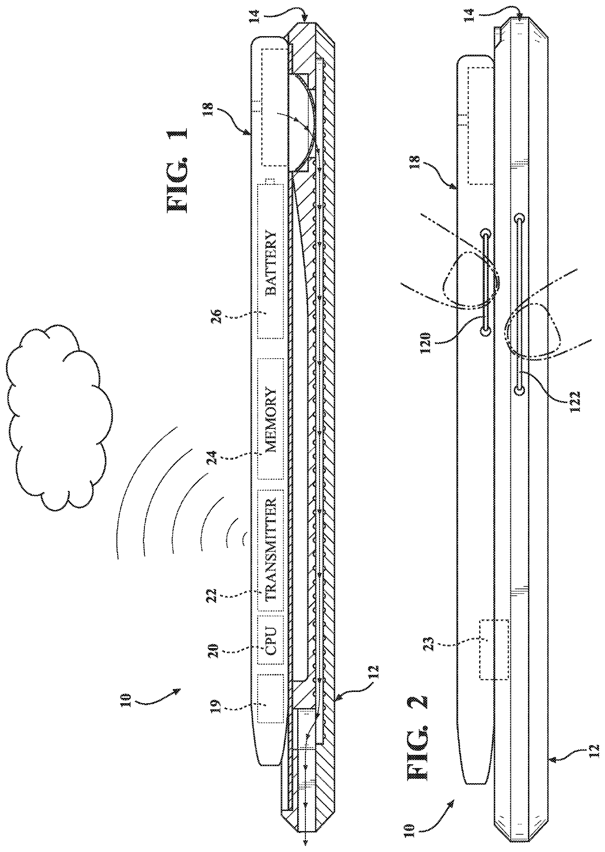
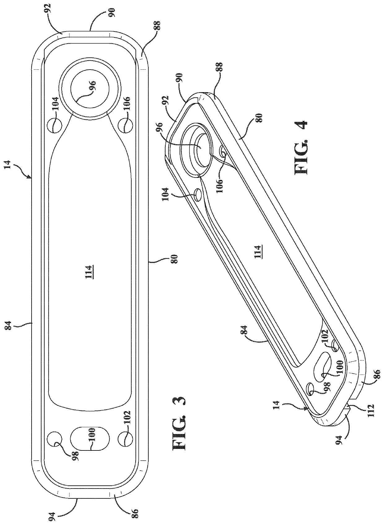
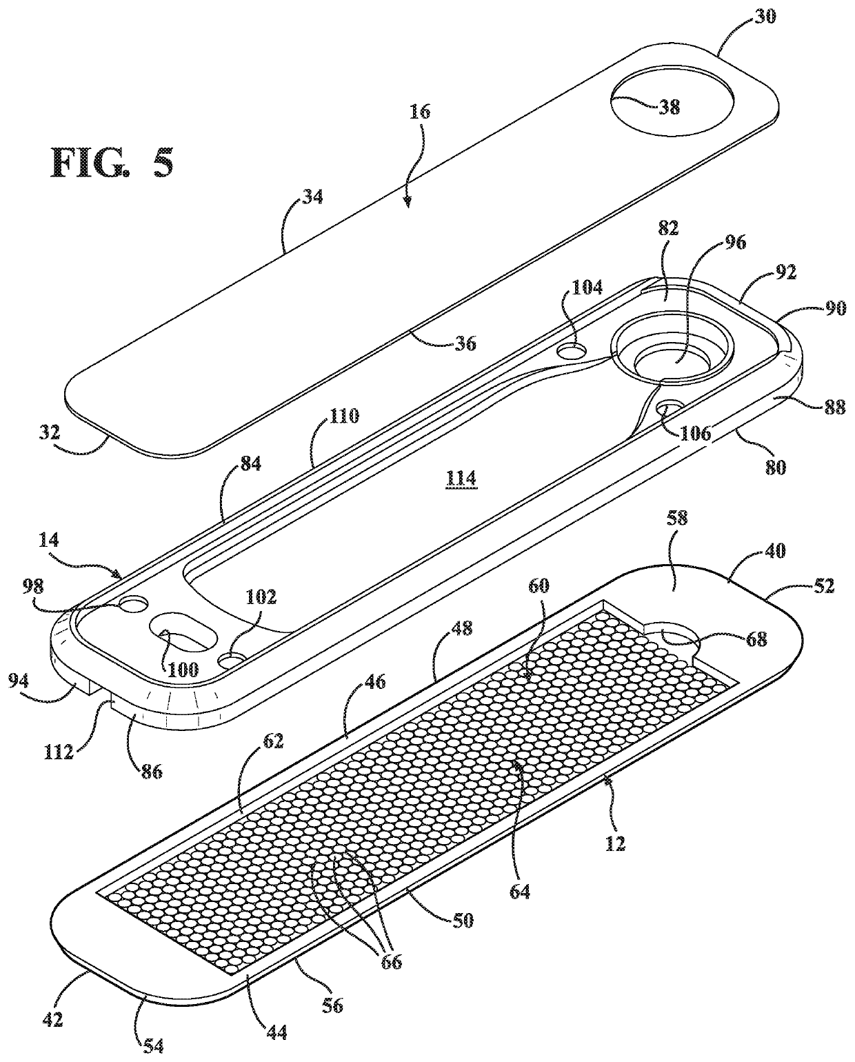
[0034]Referring to the Figures, wherein like numerals indicate like or corresponding parts, FIGS. 1 and 2, for example, illustrate a smoking device, such as vaporizers / inhalator, of the present invention, generally shown at 10. It will be apparent that multiple embodiments of this disclosure may be practiced without some or all of these specific details. In other instances, well-known process operations have not been described in detail in order not to unnecessarily obscure the present embodiments. The following description of embodiments includes references to the accompanying drawing. The drawing shows illustrations in accordance with example embodiments. These example embodiments, which are also referred to herein as “examples,” are described in enough detail to enable those skilled in the art to practice the present subject matter. The embodiments can be combined, other embodiments can be utilized, or structural, logical and operational changes can be made without departing from...


PUM


Abstract

A smoking device includes several parts such as a bottom portion, a core portion, a slide portion, and a housing. The device also includes a bowl. The slide portion presents a rectangular plate having a first end, a second end, side edges. The bottom portion includes a bottom surface and a top surface. The top surface includes a pool defined therein to form a depth and a bottom of the pool. The housing is used to hold a central processing unit, a transmitter, a memory module, and a battery, wherein all these components are operably connected with one another. The central processing unit includes a software that is configured to control dosage, temperature, length of inhaling, etc. The central processing unit is operably connected to the transmitter adaptable to receive wireless signals.

Description

RELATED APPLICATIONS[0001]This present application is a continuation in part application that claims priority to U.S. patent application Ser. No. 16 / 584,846 filed on Sep. 26, 2019 and incorporated herewith by reference in its entirety.FIELD OF INVENTION[0002]The present invention relates generally to vaporizers / inhalator having a cooling chamber that provides minimal pressure drop by creating laminar flow of smoke (inhalation material).BACKGROUND OF INVENTION[0003]The history of smoking pipes, mouthpieces, and other smoking devices is as old as the modern human history itself. There is tremendous variety of smoking devices exists across the world including those that were created specifically with the purpose of solving the problem of reducing the temperature of the smoking fumes. It is fair to say that each generation of engineers on the modern era at each new phase of progress has contributed solutions for the above stated problem. Present invention is one more step in this direct...

Claims


Application Information

Patent Timeline
IPC IPC(8): A24F40/65A24F40/20A24F40/57A24F5/00A24F40/10A24F40/42
CPCA24F40/65A24F40/20A24F40/42A24F5/00A24F40/10A24F40/57A24F3/00A24F40/50
Inventor YANKELEVICH, DMITRY
Owner YANKELEVICH DMITRY
Learn More