
Lidar system and motor vehicle

a technology of lidar system and motor vehicle, which is applied in the field of lidar system, can solve the problems of low light quantity, loss in the context of large quantity, and saturation of photodetectors, and achieve finely graduated sensitivity, increase the dynamic range of lidar system, and optimal graduated sensitivity

Pending Publication Date: 2021-11-04
ROBERT BOSCH GMBH
View PDF0 Cites 0 Cited by
  • Summary
  • Abstract
  • Description
  • Claims
  • Application Information

AI Technical Summary

Benefits of technology

The present invention relates to a lidar system that can detect both highly reflective objects in the near field and low-reflectivity objects in the far field without needing adjustments to the laser transmission power or the detector's dynamic adaptations. This improves the detection capability of photodetectors and makes it easier to furnish motor vehicles with a lidar system that has a high dynamic range.

Problems solved by technology

It can happen that with a large quantity of light, for instance highly reflective objects in the near field, photodetectors become saturated too quickly; or also that a low quantity of light, for instance from low-reflectance objects in the far field, becomes lost in the context of the large quantity of light.
It mentions the problem that a dynamic range is limited by an upper threshold above which the receiver is saturated.
This means that a darkening performance is constant over time and is not manually or automatically controllable.
If too many photons are present in the optical path, the probability increases that SPADs interconnected in an SiPM will also be saturated together at the same time and thus no longer be sensitive.

Method used


Image

  • Lidar system and motor vehicle
  • Lidar system and motor vehicle

Examples


Embodiment Construction

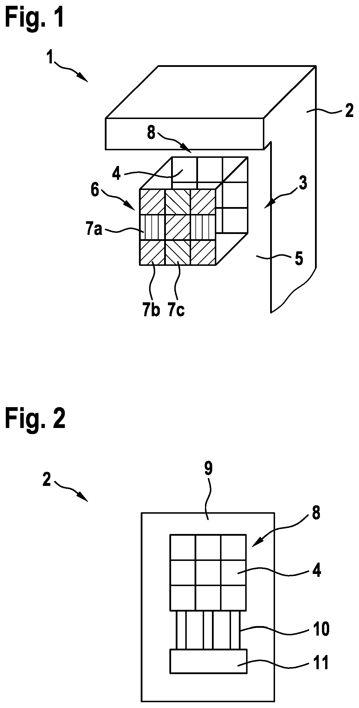
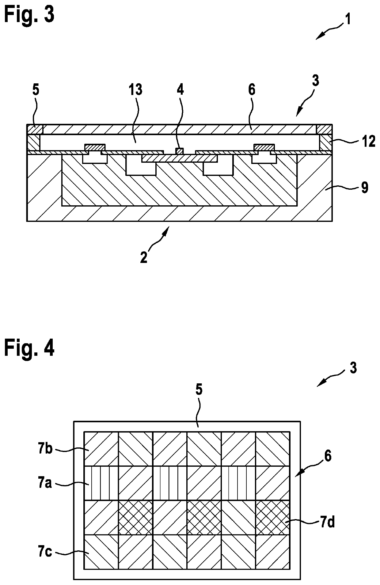
[0040]FIG. 1 shows a lidar system 1 in a first example embodiment according to the present invention. Lidar system 1 is disposed in a motor vehicle (not shown) and is operatively connected to the motor vehicle. Various details of lidar system 1 which are known to one skilled in the art have been omitted in the interest of simplification, for example a laser source that serves to emit a light beam in order to scan an environment.

[0041]Lidar system 1 depicted in FIG. 1 is configured to scan the environment with a light beam in order to acquire information about the environment, the lidar system being configured to detect both highly reflective objects in a near field of the environment and low-reflectivity objects in a far field of the environment, as will be explained in detail below.

[0042]Lidar system 1 encompasses a detector component 2 and a filter component 3. Detector component 2 encompasses several photodetectors 4, here (by way of example) nine identical photodetectors 4, that...


PUM

PropertyMeasurementUnit
distanceaaaaaaaaaa
distanceaaaaaaaaaa
distanceaaaaaaaaaa

Abstract

A lidar system that is configured to scan an environment with a light beam in order to acquire information regarding the environment is described. The lidar system is furthermore configured to detect both highly reflective objects in a near field of the environment and low-reflectivity objects in a far field regarding of the environment. The lidar system has several photodetectors that are configured to have different saturation probabilities. A motor vehicle having a lidar system of this kind which is operatively connected to the motor vehicle, is also described.

Description

FIELD[0001]The present invention relates to a lidar system that is configured to scan an environment with a light beam in order to acquire information regarding the environment, the lidar system being configured to detect both highly reflective objects in a near field of the environment and low-reflectivity objects in a far field of the environment.[0002]The present invention further relates to a motor vehicle having such a lidar system, the lidar system being operatively connected to the motor vehicle.BACKGROUND INFORMATION[0003]Lidar systems and motor vehicles of these kinds are available in principle in the related art. They have, for example, an avalanche photodiode as a photodetector, for example a single-photon avalanche diode (SPAD) or instead a silicon photomultiplier (SiPM) as a photodetector. The lidar system can have a laser source for emitting the light beam. The photodetector is arranged to receive the light beam reflected from the environment. An electronic evaluation ...

Claims


Application Information

Patent Timeline
Patent Type & Authority Applications(United States)
IPC IPC(8): G01S7/481G01S17/931G01N21/55
CPCG01S7/4816G01N21/55G01S17/931G01S7/4863G01S7/4813G01S7/4914G01S7/4868
Inventor HOLLECZEK, ANNEMARIEKAMIL, MUSTAFA
Owner ROBERT BOSCH GMBH
Learn More