High power, single-use electrical switch

Active Publication Date: 2021-10-28
RAYTHEON CO
View PDF0 Cites 0 Cited by
  • Summary
  • Abstract
  • Description
  • Claims
  • Application Information

AI Technical Summary

Benefits of technology

The patent describes a high power electrical switch that uses a spring-biased plunger contact and an insulated spacer to separate the contacts before activation. The switch is designed to be small and compact, making it suitable for use in smaller electronic assemblies with high power requirements. The method of activation involves biasing the contacts, maintaining a separation clearance, and exerting force on a tab to remove the spacer and enable engagement of the contacts. The technical effects include a more reliable and efficient electrical switch that is easy to use and adaptable for various applications.

Problems solved by technology

Due to size constraints, conventional high power switches may be deficient in smaller assemblies.

Method used


Image

  • High power, single-use electrical switch
  • High power, single-use electrical switch
  • High power, single-use electrical switch

Examples


Embodiment Construction

[0040]The principles described herein have particular application in high power electronic assemblies and systems. A high-power, single-use switch as described herein may be suitable for use in any environment, such as in underwater, air, and space environments. The switch may be configured to satisfy the requirements of a particular application, such as size, weight, power, and cooling requirements. Exemplary applications include military applications that use a single-use switch for activating a payload. Other non-military electronics applications may also be suitable.

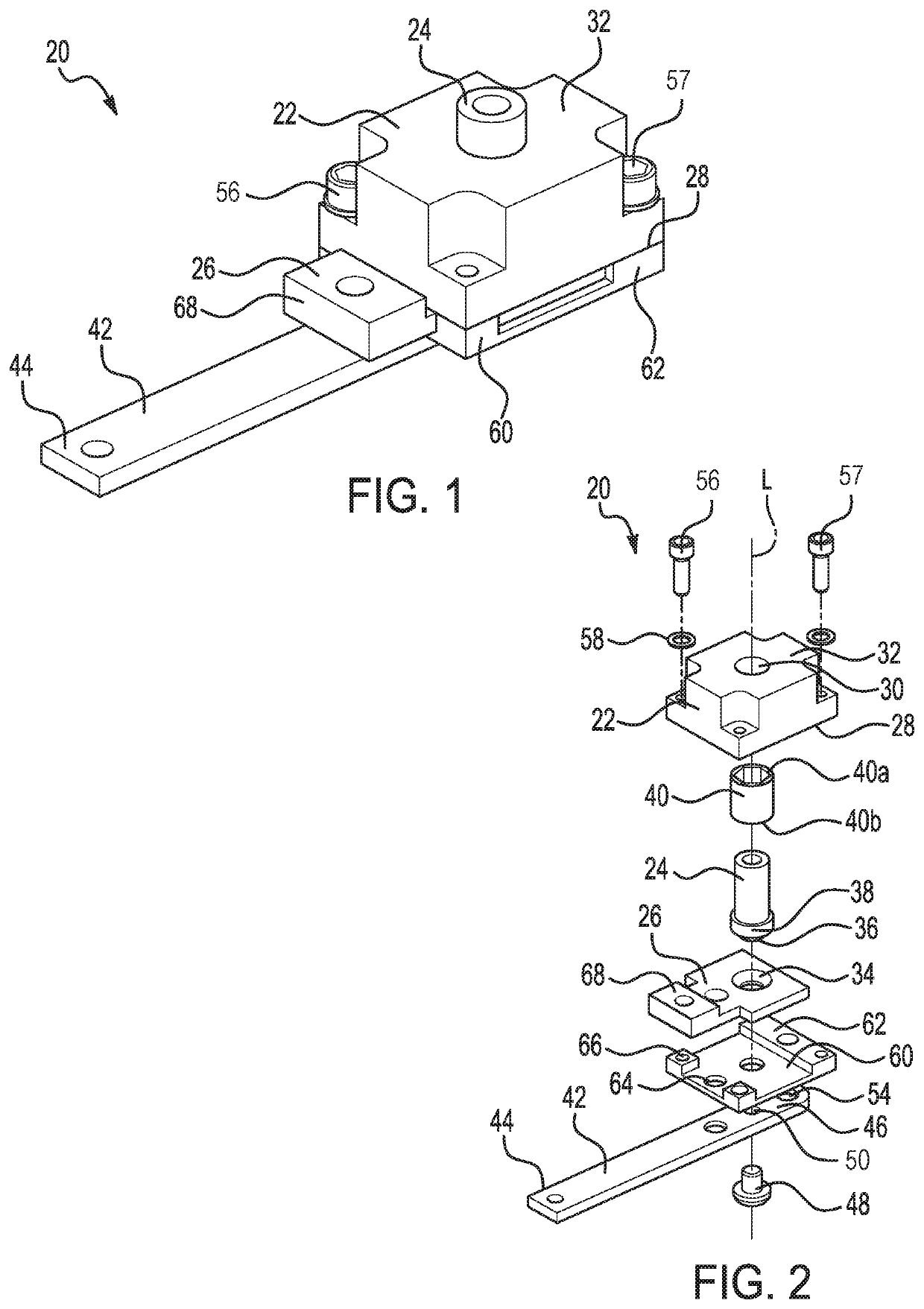
[0041]Referring first to FIGS. 1 and 2, an electrical switch 20 for activating a component of an electronic assembly is shown. FIG. 1 shows the electrical switch 20 as assembled and prior to activation. FIG. 2 shows an exploded view of the assembled electrical switch 20. The electrical switch 20 includes a cover or housing 22 that is formed of an insulating material and configured to support the components of the ele...


PUM


Abstract

A high power, single-use electrical switch includes a spring-biased plunger contact that mates with a corresponding socket contact, a spacer that provides a separation clearance between the contacts prior to activation of the switch, and a shear tab that supports the spacer and is removed from the switch to enable engagement between the contacts and activation of the switch. Using the shear tab for activation of the switch enables a compact and small form factor assembly that is suitable for use in smaller electronic assemblies.

Description

FIELD OF THE INVENTION[0001]The invention relates to an electrical switch, and more particularly to a single-use switch for a high power application.DESCRIPTION OF THE RELATED ART[0002]Various applications require single-use electrical switches for high power electronic assemblies. For example, military applications may implement a single-use switch for activation of a deployable payload. Conventional activation switches that are suitable for use with a high power assembly typically use large mechanisms that enable the switches to be used more than once. Due to size constraints, conventional high power switches may be deficient in smaller assemblies.SUMMARY OF THE INVENTION[0003]A high power, single-use electrical switch includes a spring-biased plunger contact that mates with a corresponding socket contact, an insulated spacer that provides a separation clearance between the contacts prior to activation of the switch, and a shear tab that supports the spacer and is removed from the...

Claims


Application Information

Patent Timeline
IPC IPC(8): H01H27/00
CPCH01H27/00H01H2239/062H01H2227/024H01H1/24H01H2003/0293H01H2300/046
Inventor CARLBERG, ANDREW
Owner RAYTHEON CO
Why Eureka
Try Eureka