
Driving circuit and driving method of liquid crystal display

Active Publication Date: 2021-10-28
TCL CHINA STAR OPTOELECTRONICS TECH CO LTD
View PDF0 Cites 1 Cited by
  • Summary
  • Abstract
  • Description
  • Claims
  • Application Information

AI Technical Summary

Benefits of technology

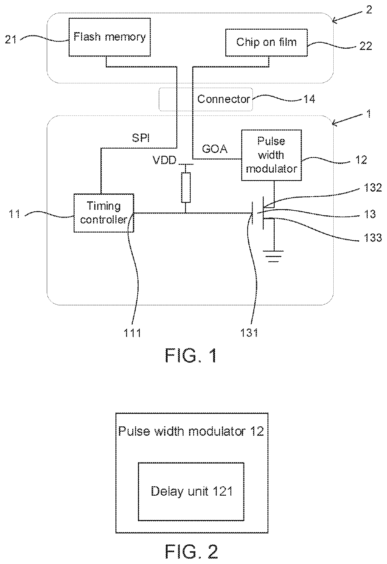
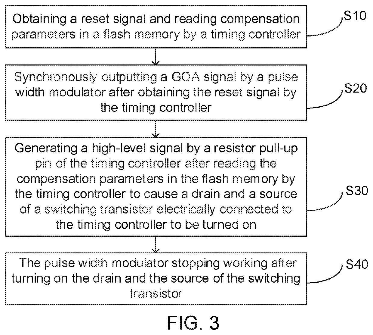
The patent describes a driving circuit and method for a liquid crystal display that improves optical compensation debugging of a production line. By using a switching transistor and resistor pull-up pin, the timing controller's reset signal is controlled by the transistor to restore the GOA signal when reading compensation parameters is completed, and to turn off the signal when the reset signal restarts. This ensures that the timing controller is not affected by the GOA signal output by a pulse width modulator when performing SPI communication with the flash memory and reduces communication time, improving the speed of optical compensation debugging.

Problems solved by technology

Once the reset signal is detected, the three-in-one pulse width modulator starts to work and continuously outputs a GOA signal, which interferes with a normal communication of the SPI.
Distorted by a clock (CK) signal in the GOA signal, resulting in distortion of the SPI signal.
At this time, the SPI communication is abnormal, and the timing controller cannot correctly read and write the Demura compensation data on the adapter board.
Therefore, how to effectively improve interference during SPI communication is an important issue in display technology.

Method used


Image

  • Driving circuit and driving method of liquid crystal display
  • Driving circuit and driving method of liquid crystal display

Examples


Embodiment Construction

[0025]The technical solutions in the embodiments of the present application will be clearly and completely described below with reference to the accompanying drawings in the embodiments of the present application. Obviously, the described embodiments are only a part of the embodiments of the present application, but not all the embodiments. Based on the embodiments in the present application, all other embodiments obtained by those skilled in the art without creative efforts fall into the protection scope of the present application.

[0026]The terms “first”, “second”, “third”, and the like (if present) in the description, claims, and the above-mentioned drawings of the present application are used to distinguish similar objects and are not necessarily used to describe a specific order or in order. It is understood that, the objects so described are interchangeable under appropriate circumstances. Furthermore, the terms “including” and “having” and any of their variations are intended ...


PUM


Abstract

A driving circuit and a driving method of a liquid crystal display are provided. By controlling a reset signal of a timing controller through a switching transistor, a GOA signal is recovered when reading compensation parameters is completed, and the GOA signal is turned off when the reset signal is restarted. Therefore, the timing controller is not affected by the GOA signal output by a pulse width modulator when performing SPI communication with a flash memory. In addition, this reduces communication time, thereby improving speed of optical compensation debugging of a production line.

Description

CROSS-REFERENCE TO RELATED APPLICATION[0001]This application claims the priority of Chinese Application No. 201911187281.5 filed on Nov. 28, 2019 and titled “DRIVING CIRCUIT AND DRIVING METHOD OF LIQUID CRYSTAL DISPLAY”, which is incorporated herein by reference in its entirety.FIELD OF INVENTION[0002]The present disclosure relates to the field of display technologies, and more particularly to a driving circuit and a driving method of a liquid crystal display.BACKGROUND OF INVENTION[0003]When a display panel is undergoing optical compensation debugging on a production line, a timing controller on a main control board communicates with an adapter board through a serial peripheral interface (SPI). A chip on film (COF) and a flash memory are disposed on the adapter board. Each time, after the timing controller reads and writes Demura compensation data in the flash memory, the timing controller needs to use a reset signal to achieve a highly efficient restart operation. The timing contr...

Claims


Application Information

Patent Timeline
IPC IPC(8): G09G3/36
CPCG09G3/3648G09G2310/061G09G2310/08G09G3/3611G09G2310/0245G09G2320/064
Inventor WU, MIAOFA
Owner TCL CHINA STAR OPTOELECTRONICS TECH CO LTD
Learn More