
Method for connecting an energy storage module to a module support, in particular a cooling element

a technology of energy storage modules and support structures, applied in the direction of sustainable manufacturing/processing, climate sustainability, final product manufacturing, etc., can solve the problems of not always being able to set equal tightening conditions for all screw connections, the type of fastening of energy storage modules or modules is problematic, and the gap can be relatively larg

Active Publication Date: 2021-10-21
AUDI AG
View PDF7 Cites 0 Cited by
  • Summary
  • Abstract
  • Description
  • Claims
  • Application Information

AI Technical Summary

Benefits of technology

The patent describes a method for compressing a substance in a workshop using special screws. This method allows for the application of high forces to move the energy storage module and compress the compound in a way that it fills the gap without being obstructed by tolerance compensation elements. The use of the screws ensures solid compression and a small gap width, which is important for the safe and effective use of the energy storage module. This method is easy to implement and does not require any additional equipment or restrictions on the gap width.

Problems solved by technology

This type of fastening the energy storage module or modules is problematic insofar as cases of soft screws can occur during the tightening of the screws, i.e., the screw head can be screwed slightly into the soft surface, for example of the housing of the energy storage module.
Setting equal tightening conditions over all screw connections is therefore not always possible, there are cases in which reworking is necessary.
Furthermore, often only a relatively large gap can be set by this system.
Such a connecting technique can be selected at the factory, but not on location in the workshops, since a corresponding press is not available there.
If an attempt is made using the typical connecting screws while using such tolerance compensation elements to screw down the energy storage module and simultaneously to compress the compound, this would thus not result in complete distribution of the compound, since the tolerance compensation elements would quasi-freeze the gap existing at the start of the screwing down, since the second section is unscrewed from the first during the screwing down as soon it presses against the bottom of the energy storage module, which would limit the further compression movement.
In any case, however, the second sections of the tolerance compensation elements are actuated and unscrewed, thus run against the bottom of the energy storage module and thus clamp the tolerance compensation element between the module support and the energy storage module.

Method used


Image

  • Method for connecting an energy storage module to a module support, in particular a cooling element
  • Method for connecting an energy storage module to a module support, in particular a cooling element
  • Method for connecting an energy storage module to a module support, in particular a cooling element

Examples


Embodiment Construction

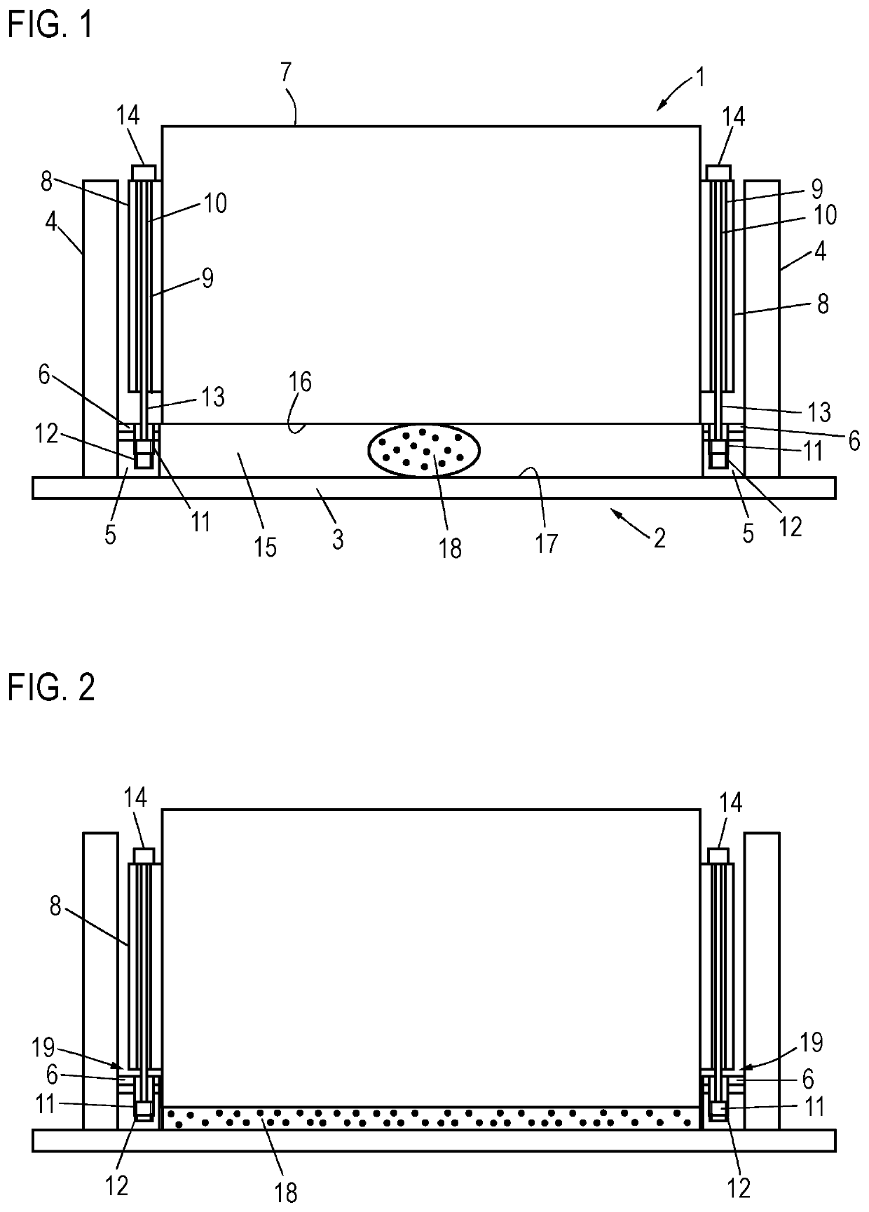
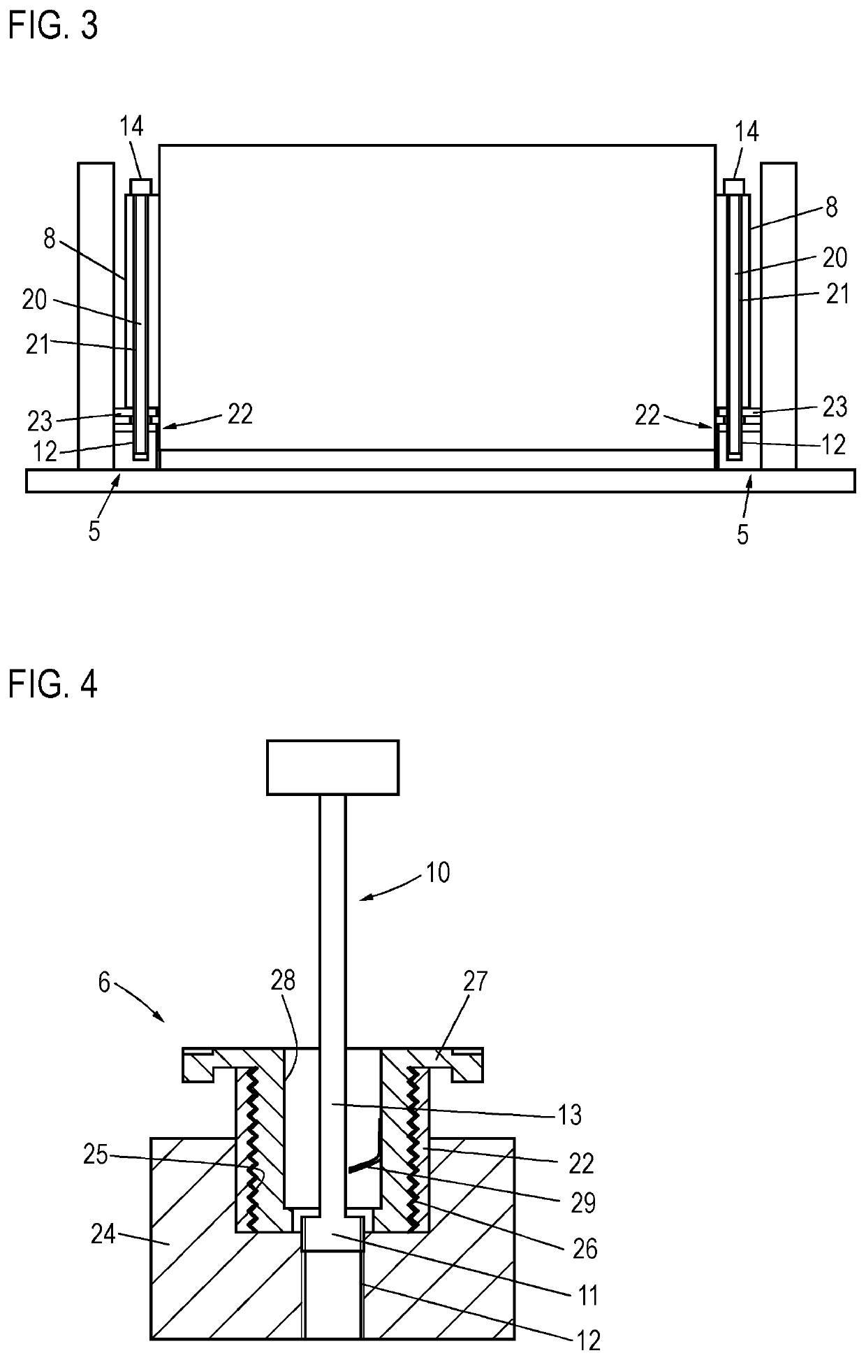
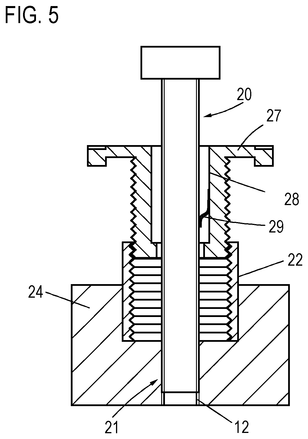
[0021]FIG. 1 shows an energy storage module 1 and a module support 2, for example a cooling plate 3, which has two side walls 4 and two wall sections 5, on which multiple compensation elements 6, two of which are shown here, which are also described in detail hereinafter, are arranged. Each tolerance compensation element 6 has a first section, which is screwed in on the respective wall section 5, for example into a suitable threaded bore, and fixed therein. Furthermore, each tolerance compensation element 6 has a second section, which can be screwed down via a threaded connection relative to the first section and is unscrewed from the first section upon the placement of a connecting screw.

[0022]The energy storage module 2 itself has a housing 7, on which two housing sections 8 are provided in the example shown, which have a corresponding passage 9, through each of which a compression screw 10 is guided in the example shown. This compression screw 10 has in each case a threaded secti...


PUM

PropertyMeasurementUnit
forceaaaaaaaaaa
thermally-conductiveaaaaaaaaaa
widthaaaaaaaaaa

Abstract

A method for connecting an energy storage module to a module support, in particular a cooling element, The energy storage module is fastened on the module support by multiple connecting screws, which are each screwed into threaded bores provided on the module support. A gap is provided between the bottom of the energy storage module and the bottom of the module support, into which a thermally-conductive compound is introduced, which is distributed to fill the gap due to a reduction of the gap width when the energy storage module is screwed down.

Description

FIELD[0001]The invention relates to method for connecting an energy storage module to a module support, in particular a cooling element, wherein the energy module is fastened on the module support by means of multiple connecting screws, which are each screwed into threaded bores provided on the module support, and wherein a gap is provided between the bottom of the energy storage module and the bottom of the module support, into which a thermally-conductive compound is introduced, which is distributed to fill the gap when the energy storage module is screwed on as a result of a reduction of the gap width.BACKGROUND[0002]Electrically-operated motor vehicles require one or more energy storage devices, also called batteries, which typically comprise a plurality of individual energy storage modules. These modules are fixedly connected to a module support, in particular a cooling element, via which cooling of the energy storage modules is possible. Introducing a thermally-conductive comp...

Claims


Application Information

Patent Timeline
Patent Type & Authority Applications(United States)
IPC IPC(8): H01M10/04H01M10/613H01M10/6554
CPCH01M10/04B60L50/66H01M10/6554H01M10/613H01M10/625H01M10/653H01M10/655Y02P70/50Y02E60/10H01M50/262
Inventor SCHIELER, OLIVERSIMON, MARTIN
Owner AUDI AG
Learn More