
Method of identifying a source component of particulate debris in an aircraft engine

a technology of particulate debris and source components, which is applied in the field of maintenance and diagnostic of aircraft engines, can solve problems such as particle material in engine fluids

Active Publication Date: 2021-10-21
PRATT & WHITNEY CANADA CORP 1
View PDF0 Cites 2 Cited by
  • Summary
  • Abstract
  • Description
  • Claims
  • Application Information

AI Technical Summary

Benefits of technology

The patent is about a method and system for identifying the source of debris collected from an aircraft engine. The method involves analyzing the composition of the debris, identifying the presence of certain elements, and matching the debris to components made of the same material family. This allows for the identification of the source component of the debris. The technical effect is better understanding the composition of the debris, which can aid in identifying the source and cause of the damage.

Problems solved by technology

However, in some cases, the presence of particulate material in an engine fluid can be a sign of premature wear of a component or of another condition which should trigger engine maintenance.

Method used


Image

  • Method of identifying a source component of particulate debris in an aircraft engine
  • Method of identifying a source component of particulate debris in an aircraft engine
  • Method of identifying a source component of particulate debris in an aircraft engine

Examples


Embodiment Construction

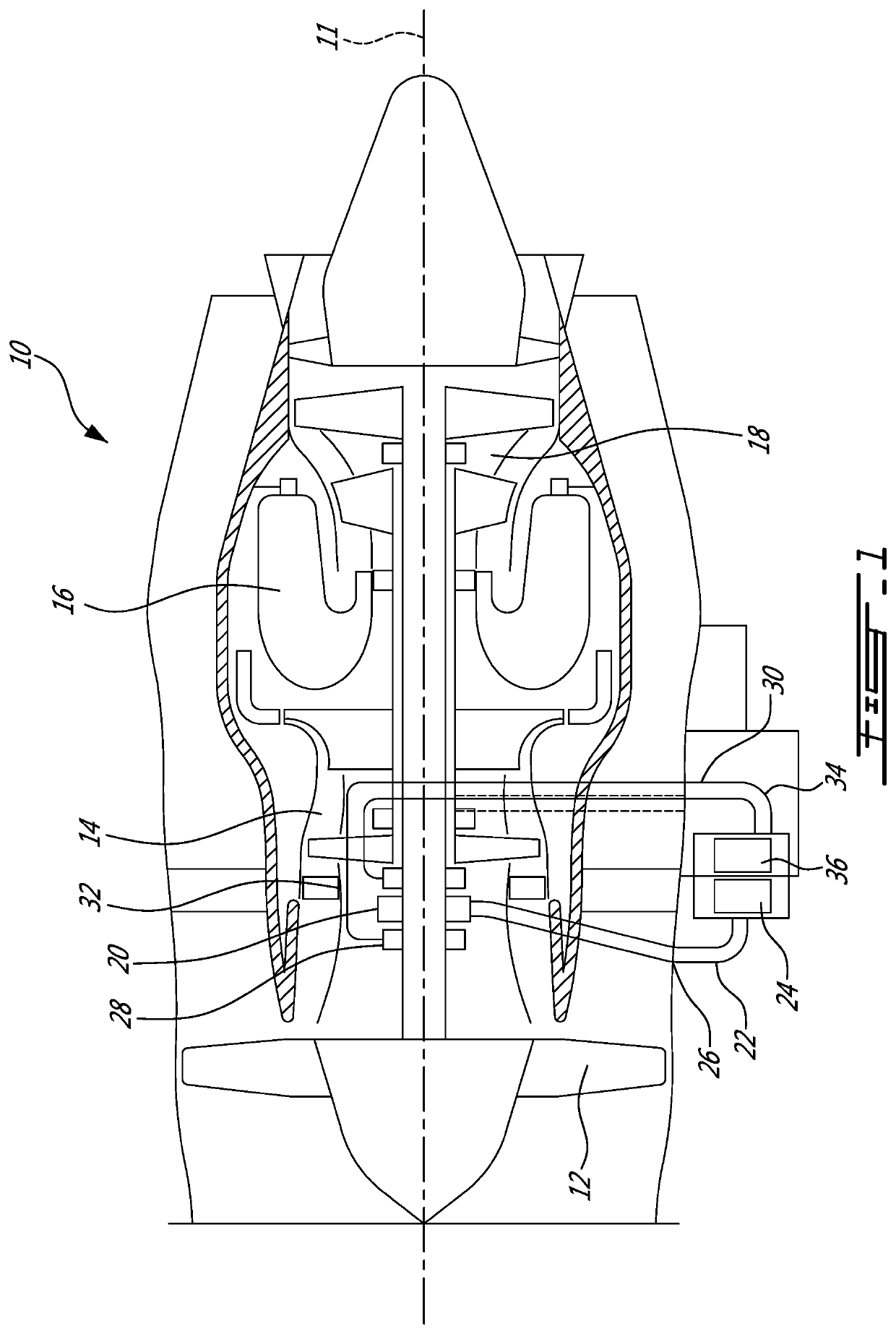
[0014]FIG. 1 illustrated a gas turbine engine 10 of a type preferably provided for use in subsonic flight, generally comprising in serial flow communication a fan 12 through which ambient air is propelled, a compressor section 14 for pressurizing the air, a combustor 16 in which the compressed air is mixed with fuel and ignited for generating an annular stream of hot combustion gases, and a turbine section 18 for extracting energy from the combustion gases.

[0015]The compressor 14, fan 12 and turbine 18 have rotating components which can be mounted on one or more shafts. Bearings 20 are used to provide smooth relative rotation between a shaft and casing (non-rotating component), and / or between two shafts which rotate at different speeds. An oil lubrication system 22 including an oil pump 24, sometimes referred to as a main pump, and a network of conduits and nozzles 26, is provided to feed the bearings 20 with oil. Seals 28 are used to contain the oil. A scavenge system 30 having cav...


PUM

PropertyMeasurementUnit
compositionaaaaaaaaaa
concentrationaaaaaaaaaa
compositionsaaaaaaaaaa

Abstract

The method can include analyzing the composition of the particulate metal debris, including ascertaining a presence of at least one main alloy element and a presence or absence of at least one signature alloy element in the particulate debris; establishing a correlation between the particulate metal debris and a set of components, including matching the ascertained presence of the at least one main alloy element to a family of alloys from which the components of the set, including the source component, are made; and determining the source component amongst the components of the set, including matching the ascertained presence or absence of the at least one signature alloy element to an alloy composition of the source component.

Description

TECHNICAL FIELD[0001]The application relates generally to maintenance and diagnostic of aircraft engines and, more particularly, to a method of identifying a source component of particulate debris.BACKGROUND OF THE ART[0002]In aircraft engine, some components are designed to progressively wear during engine operation and eventually be replaced. The presence of particulate material of such components in engine fluids can be normal and non-alarming. However, in some cases, the presence of particulate material in an engine fluid can be a sign of premature wear of a component or of another condition which should trigger engine maintenance. By determining the nature of the debris (e.g. metal, carbon, polymer), one can obtain an indication of the nature of the engine condition, and can guide maintenance personnel in efficiently performing engine maintenance.[0003]Even though known methods were satisfactory to a certain degree, there remained room for improvement. In particular, there rema...

Claims


Application Information

Patent Timeline
Patent Type & Authority Applications(United States)
IPC IPC(8): G01N33/2028G01N33/28G01M15/14
CPCG01N33/2028G01M15/14G01N33/2888
Inventor BRILLON, LOUIS
Owner PRATT & WHITNEY CANADA CORP 1
Learn More