
Hydraulic Mantle Assembly System for a Gyratory Rock Crusher

a technology of hydraulic mantle and gyratory rock crusher, which is applied in the field of hydraulic mantle assembly system for gyratory rock crusher, can solve the problems of increasing the risk of head nut loosening, affecting the operation of the gyratory rock crusher,

Pending Publication Date: 2021-10-21
TECHNOFAST IND
View PDF0 Cites 2 Cited by
  • Summary
  • Abstract
  • Description
  • Claims
  • Application Information

AI Technical Summary

Benefits of technology

The present invention allows for quick and safe replacement of a worn and deformed mantle of a gyratory rock crusher. This is possible without using the often dangerous and inefficient heating and beating techniques of the prior art. Instead, a hydraulic tightening and loosening process is employed, making it easy to remove and replace even severely damaged and deformed mantles. This results in improved safety and efficiency for the workers involved in the process.

Problems solved by technology

During normal use, both the concave, mantle and head nut can suffer significant wear and require replacement.
The action of crushing rocks against the crushing chamber generally plastically deforms and axially lengthens the mantle, which adds significant tension to the head nut.
Due to the plastic deformation in the system, loosening the head nut and replacing the mantle is generally a time consuming, dangerous and expensive process.
The associated down-time and loss of productivity of the rock crusher during the mantle replacement process often adds greatly to the overall cost of the process.
Further, due to their large size the head nuts are typically difficult to tighten and loosen in the confined space within the body of the gyratory crusher.
Such practices are difficult and dangerous owing to the conditions and spatial restrictions in which the operations must be performed.
The use of flame cutting torches can ignite the compounds, thereby creating a fire danger and health hazard.

Method used


Image

  • Hydraulic Mantle Assembly System for a Gyratory Rock Crusher
  • Hydraulic Mantle Assembly System for a Gyratory Rock Crusher
  • Hydraulic Mantle Assembly System for a Gyratory Rock Crusher

Examples


Embodiment Construction

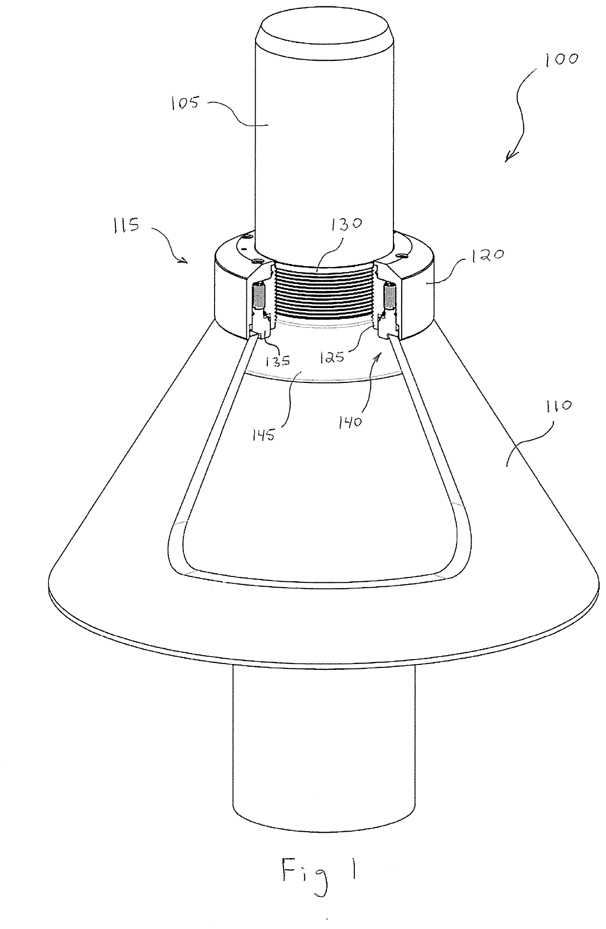
[0035]The present invention relates to a hydraulic mantle system for a hydraulic rock crusher. Elements of the invention are illustrated in concise outline form in the drawings, showing only those specific details that are necessary to understanding the embodiments of the present invention, but so as not to clutter the disclosure with excessive detail that will be obvious to those of ordinary skill in the art in light of the present description.

[0036]In this patent specification, adjectives such as first and second, left and right, above and below, top and bottom, upper and lower, rear, front and side, etc., are used solely to define one element or method step from another element or method step without necessarily requiring a specific relative position or sequence that is described by the adjectives. Words such as “comprises” or “includes” are not used to define an exclusive set of elements or method steps. Rather, such words merely define a minimum set of elements or method steps ...


PUM


Abstract

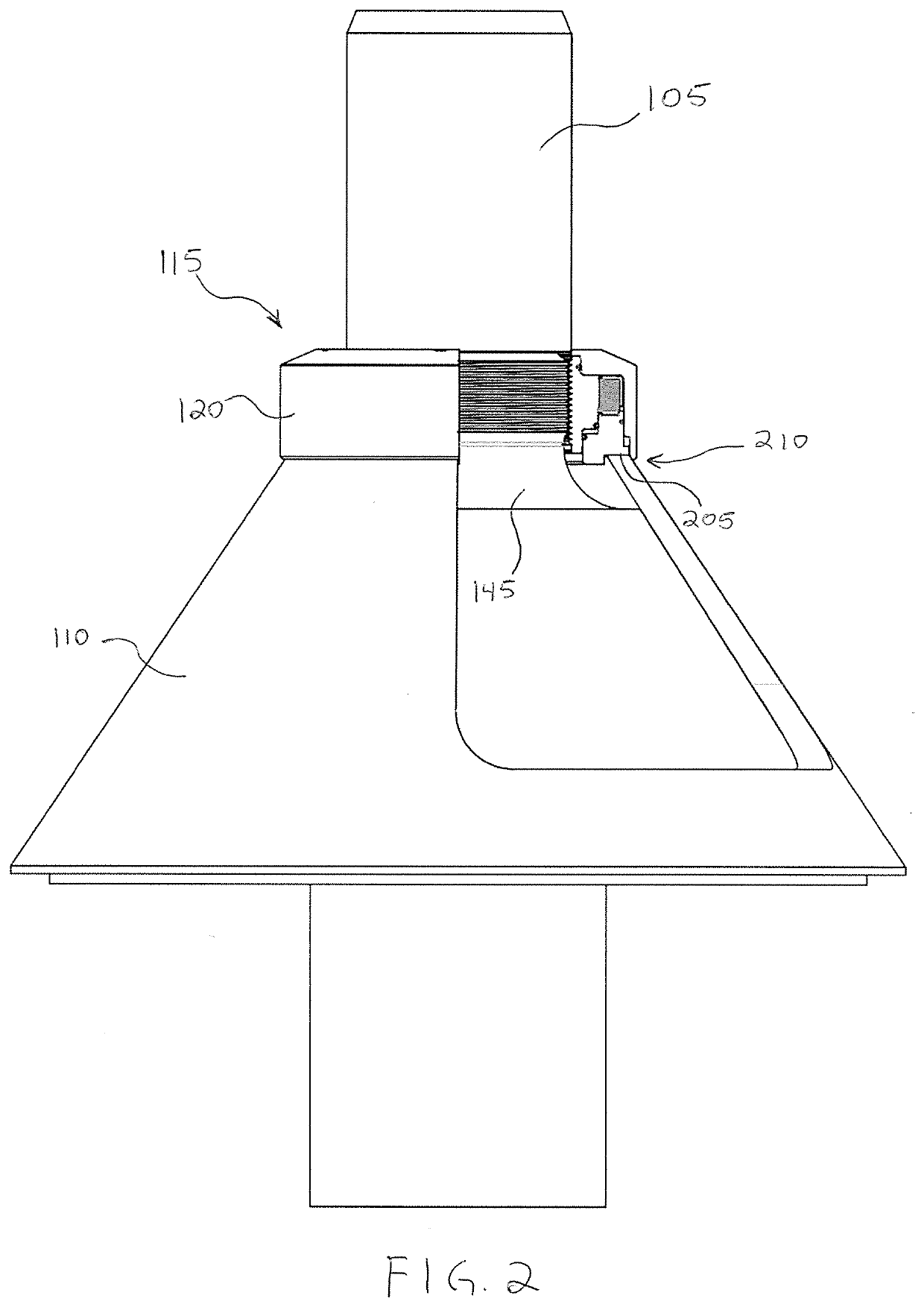
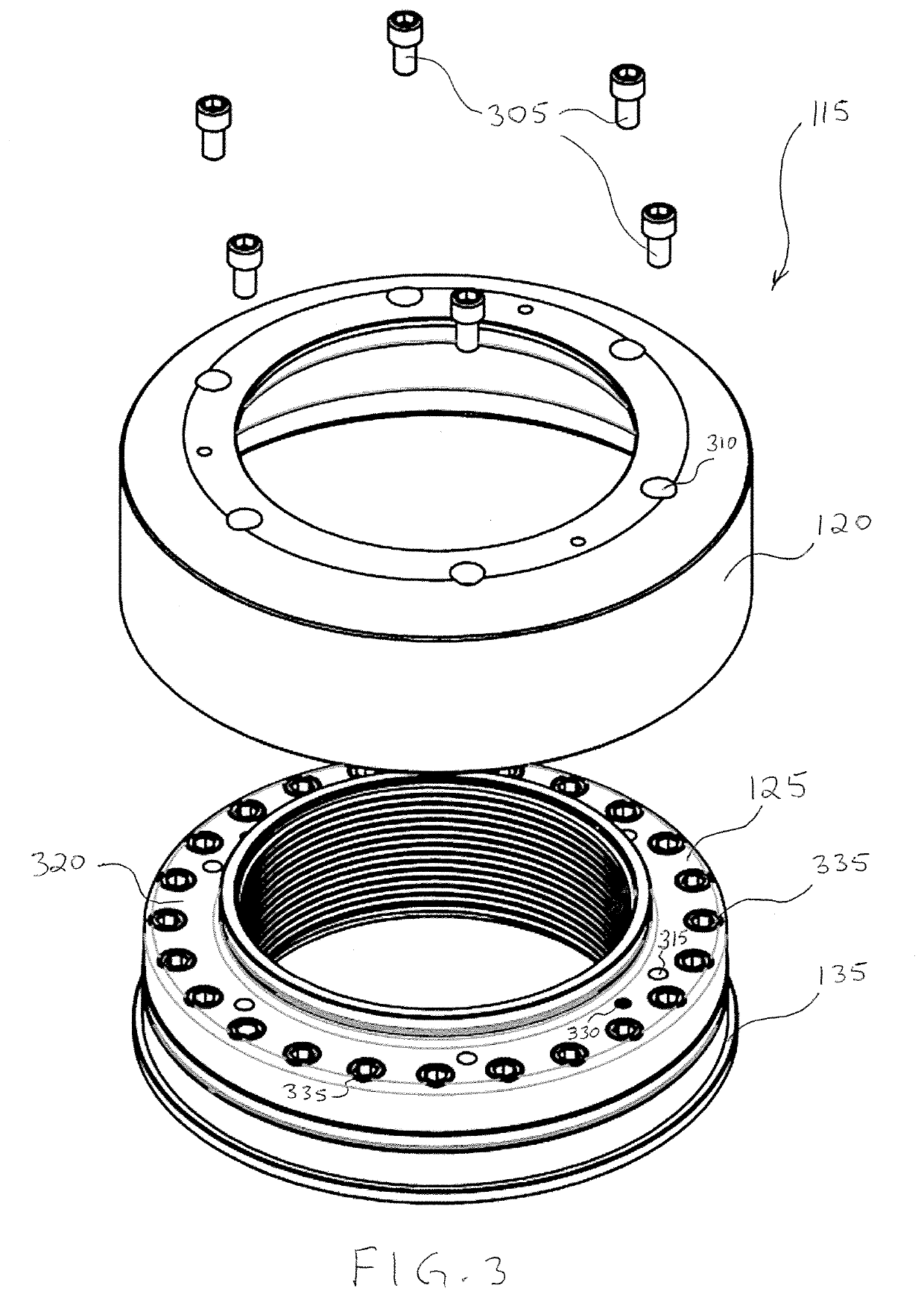
A hydraulic mantle system for a gyratory rock crusher enables the safe, quick and efficient replacement of a worn or deformed mantle. The system includes a main shaft, an annular nut, an annular hydraulic piston and an annular mantle. The main shaft has a flange and external threads adjacent the flange. The annular nut body has side surfaces and internal threads that are threaded onto the external threads of the main shaft. The annular hydraulic piston has side surfaces that slidingly engage the side surfaces of the annular nut body. The annular mantle has an upper neck portion and a lower edge portion. The main shaft extends extending through the upper neck portion. The upper neck portion of the annular mantle is compressed between the flange of the main shaft and the annular hydraulic piston.

Description

FIELD OF THE INVENTION[0001]The present invention relates generally to systems and methods for assembling a mantle in a gyratory rock crusher, and in particular to systems and methods for applying tensile force during assembly and disassembly of gyratory rock crusher mantle systems.BACKGROUND[0002]Rock crushers are commonly used in mining applications in order to reduce large rocks to smaller rocks, gravel or dust, depending on the rock type and required end use. A gyratory rock crusher is a popular type of crusher that employs a funnelled crushing chamber, known as a concave, that guides input rock to centre hole. A mantle system is suspended inside the centre hole and includes a main shaft and a mantle attached to the main shaft.[0003]The main shaft is generally connected to an actuating system below the crushing chamber, which through the use of belts or eccentric gears swings the main shaft and mantle through a gyratory motion adjacent lower edges of the crushing chamber. Rocks ...

Claims


Application Information

Patent Timeline
IPC IPC(8): B02C2/06
CPCB02C2/06B02C2/04B02C2210/02B02C2/005
Inventor BUCKNELL, JOHN WENTWORTHBUCKNELL, ROBERT WENTWORTH
Owner TECHNOFAST IND
Learn More