Connector module

Active Publication Date: 2021-10-07
HOSIDEN CORP
View PDF1 Cites 4 Cited by
  • Summary
  • Abstract
  • Description
  • Claims
  • Application Information

AI Technical Summary

Benefits of technology

The patent text describes a need for a connector module that is durable, easily alignable with a connection target instrument, and provides high shielding performance. The seal member helps ensure a tight seal, but a gap formed by the seal member allows for easy positioning of the connector module with the target instrument. Overall, the patent aims to improve the connection between electronic instruments.

Problems solved by technology

On the other hand, the connector module disclosed in Japanese Unexamined Patent Application No. 2007-127206 is capable of absorbing positional displacement between the connection target instrument and the connector, thanks to the flexible thin film member, yet this flexible thin film member is problematic in its strength.
Yet, there is a risk of the tubular movable shell coming into repeated contacts with the tubular outer shell due to e.g. vibration, which causes a problem relating to durability.
Moreover, this connector module disclosed in Japanese Unexamined Patent Application No. 2014-137913 is not able to maintain a fixed distance between the tubular movable shell and the tubular outer shell, thus it is difficult to achieve an impedance matching, thus presenting possibility of giving adverse influence to high frequency propagation performance.
fixing of the connector case to the main body case via the fastener member causing, in the connector, elastic deformation of the elastic piece, resulting in decrease in a gap between the first member and the second member, consequently in establishment of electrical connection between the first member and the second member.

Method used


Image

  • Connector module
  • Connector module
  • Connector module

Examples


first embodiment

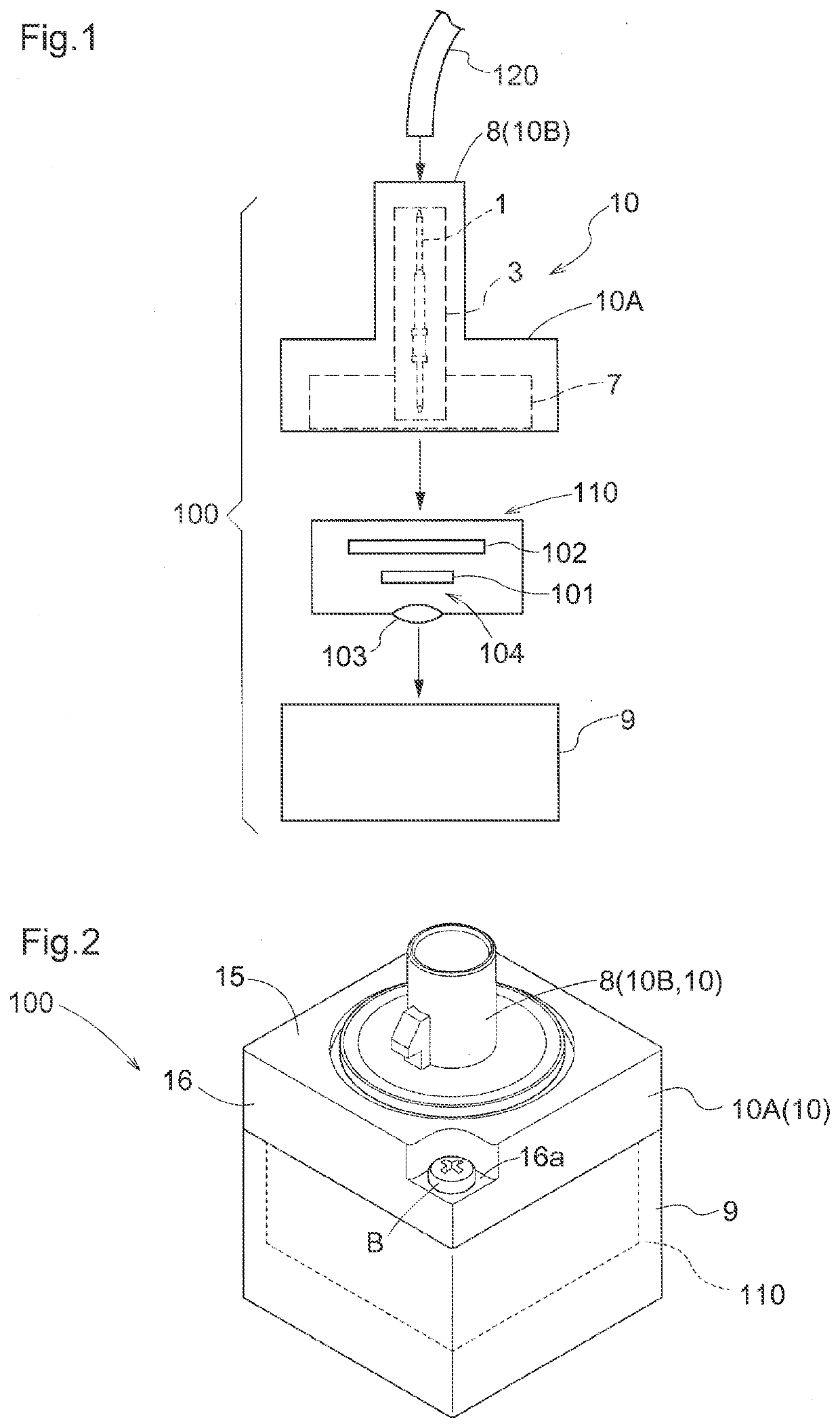
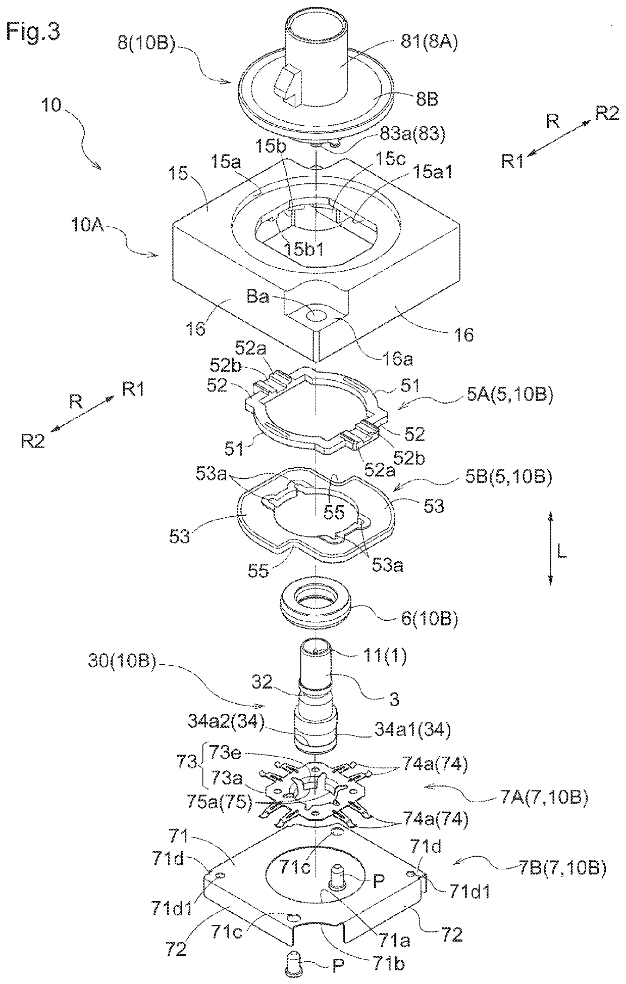
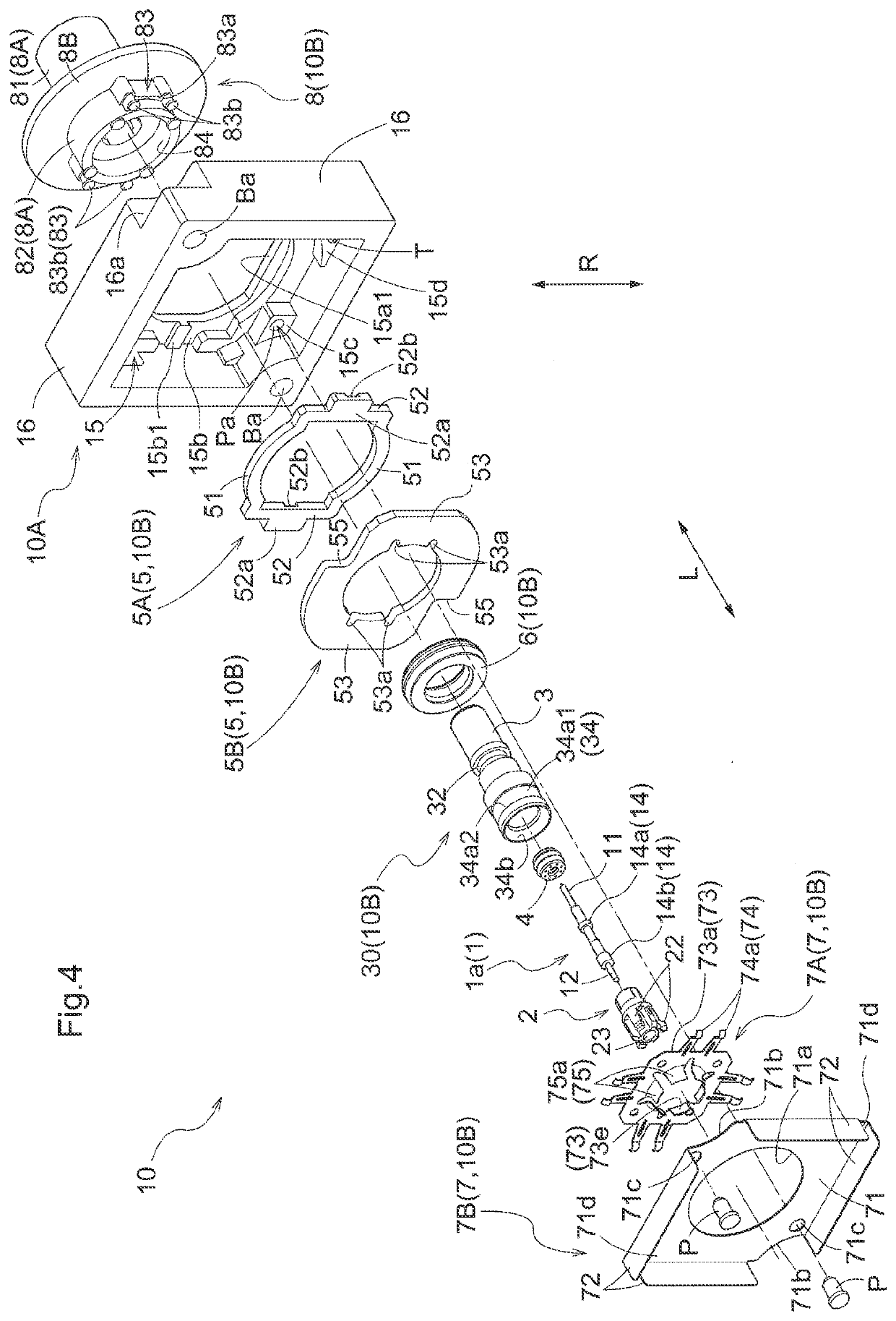
[0043]FIG. 2 shows an overall perspective view of the camera unit 100. FIGS. 3-4 show exploded perspective views of the connector module 10. FIG. 5 shows a vertical section of the connector module 10. As shown in FIG. 2, the connector module 10 includes a connector case 10A and a connector 10B inserted in the connector case 10A. The connector case 10A and the main body case 9 are fixed to each other via a plurality of (two in this embodiment) bolts B (an example of “fastener member”). As shown in FIG. 3, the connector 10B includes a housing 8, a terminal module 30, an outer seal member 6, a shield case 7 and a rotation-preventing mechanism 5 (an example of “rotation-preventing member”). Further, as shown in FIG. 4, the terminal module 30 includes a center conductor 1 (or a core conductor; an example of “conductor”), a holder 2, a tubular shell 3 and an inner seal member 4. The terminal module 30 has similar functions to those of the coaxial cable 120 described above. The center cond...

second embodiment

[0072]Next, with reference to FIGS. 7 through 9, a connector module 10 relating to a second embodiment will be explained in details. Incidentally, in the following discussion, those effects, functions and members having similar to those of the first embodiment will be explained with using the same or like reference signs and numerals for the sake of convenience. The connector module 10 relating to the second embodiment differs from the first embodiment in that this module 10 does not include the rotation-preventing mechanism 5, but includes an annular seal member S.

[0073]As shown in FIG. 9, the connector module 10 includes a connector case 10A and a connector 10B. The connector 10B includes a housing 8, a terminal module 30, an outer seal member 6, a shield case 7, and an annular seal member S (an example of “seal member”). Further, the terminal module 30 includes a center conductor 1, a holder 2, a tubular shell 3 and an inner seal member 4.

[0074]As shown in FIGS. 7-8, the center c...


PUM


Abstract

Provided is a connector module that is highly durable and that also allows easy position alignment with a connection target instrument while maintaining high shielding performance. The connector module includes a connector case and a connector inserted in the connector case. The connector includes a contact, a holder, a conductive tubular shell, a housing and a conductive shield case. The shield case includes a first member having an elastic portion and a second member in the form of a bottomed tube. The first member forms an elastic piece contactable with the second member. Fixing of the connector case to a main body case via a fastener member causes, in the connector, elastic deformation of the elastic piece, resulting in decrease in a gap between the first member and the second member, consequently in establishment of electrical connection between the first member and the second member.

Description

CROSS REFERENCE TO RELATED APPLICATION[0001]This application is based on and claims priority under 35 U.S.C. Section 119 to Japanese Patent Application No. 2020-69272 filed on Apr. 7, 2020, the entire content of which are incorporated herein by reference.TECHNICAL FIELD[0002]This disclosure relates to a connector module to be electrically connected to a connection target instrument.BACKGROUND ART[0003]Conventionally, there is known a connector module to be electrically connected to a connection target instrument such as a camera module (see e.g. Japanese Unexamined Patent Application No. 2019-67740 publication). The connector module disclosed in Japanese Unexamined Patent Application No. 2019-67740 publication includes a connector case fixed to a main body case of the connection target instrument and a connector accommodated in the connector case (“terminal module” in the document). The connector includes a contact (“center conductor” in the document), an insulator holder supporting...

Claims


Application Information

Patent Timeline
IPC IPC(8): H01R13/6581H01R13/512H01R13/432H01R13/52H01R13/6596H01R24/40
CPCH01R13/6581H01R13/512H01R24/40H01R13/521H01R13/6596H01R13/432H01R13/6315H01R13/6582H01R13/639H01R13/6215H01R13/748H01R13/5202H01R12/91H01R2201/26H01R2103/00H01R24/542H01R13/6583H01R13/6597H05K9/0018H04N23/50H04N23/57
Inventor KATO, RYUHEI
Owner HOSIDEN CORP
Why Eureka
Try Eureka