Electric inertia control apparatus

a control apparatus and inertia technology, applied in the direction of instrumentation, machine parts testing, structural/machine measurement, etc., can solve the problem of limited control bandwidth, suppress the resonance of mechanical systems, and achieve high accuracy the effect of simulation, and prolonging the control respons

Active Publication Date: 2021-10-07
MEIDENSHA ELECTRIC MFG CO LTD
View PDF0 Cites 0 Cited by
  • Summary
  • Abstract
  • Description
  • Claims
  • Application Information

AI Technical Summary

Benefits of technology

The present invention is an electric inertia control device that can suppress the resonance phenomenon in a mechanical system, even when the test piece or the set inertia is changed. The device includes an inertia compensator that generates an inertia compensation torque signal based on the higher-level torque command signal and the shaft torque detection signal. The inertia compensation torque signal is directly fed back to generate the inertia compensation torque signal. The device also includes a resonance suppression control device that uses the inertia compensation torque signal and the shaft torque detection signal to generate a torque current command signal. The device includes a set value acquiring unit that acquires both the set inertia and the test piece inertia, and a selector that selects one of the plurality of control modules based on the set inertia and the test piece inertia. The device incorporates a plurality of control modules with different input / output characteristics, and each control module is designed to perform a resonance suppression control function. The device utilizes a controller designed by a computer to realize the resonance suppression control, and the control module satisfies a predetermined design condition in a feedback control system. The device can perform high electric inertia control with a high control response even when the test piece or the set inertia is changed.

Problems solved by technology

However, in the electric inertia control device 100 of FIG. 11, a plurality of integrators are present, and thus a significant control delay occurs, with the result that the enhancement of a control bandwidth is limited depending on the degree of equipment resonance.

Method used


Image

  • Electric inertia control apparatus
  • Electric inertia control apparatus
  • Electric inertia control apparatus

Examples


Embodiment Construction

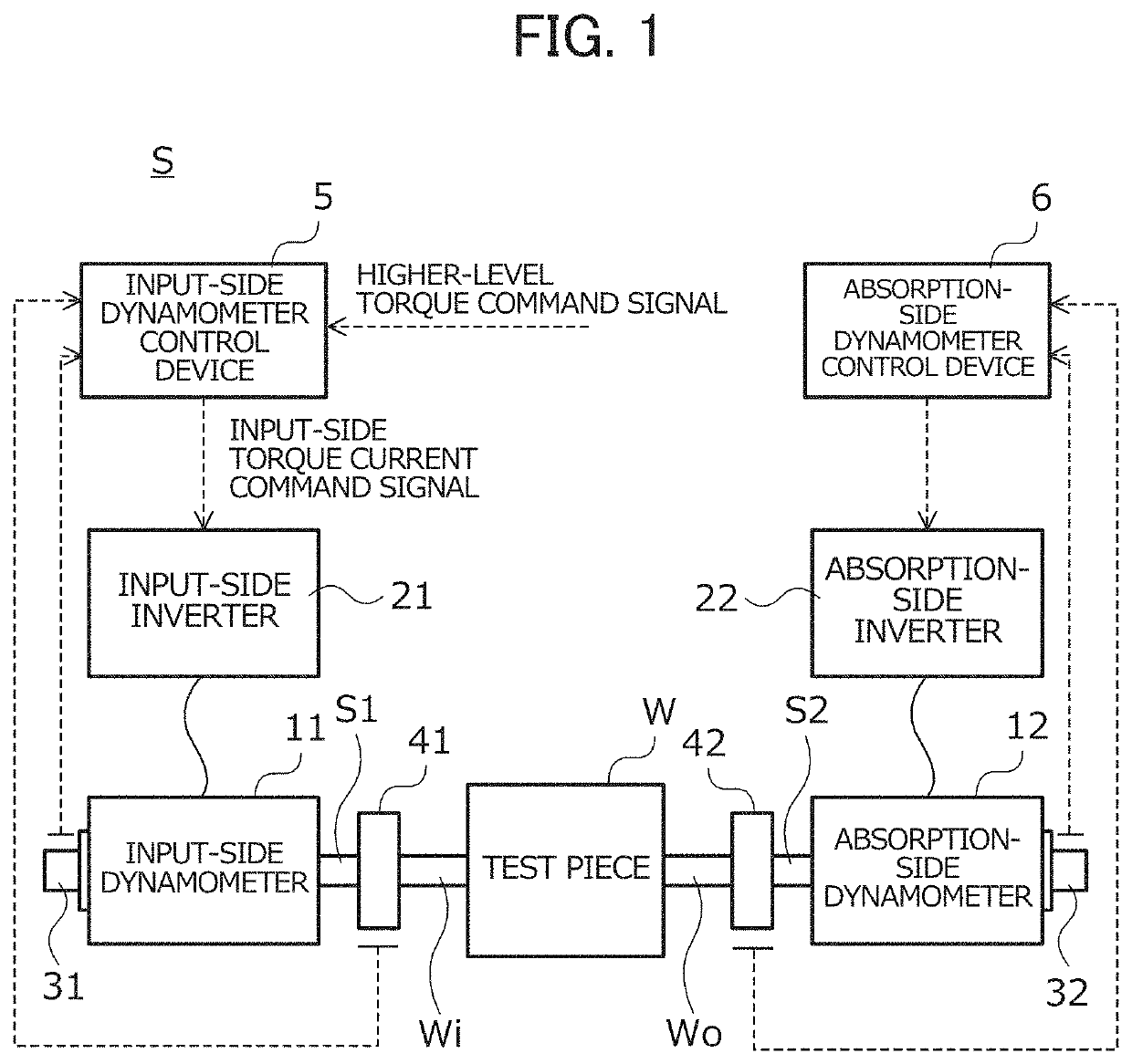
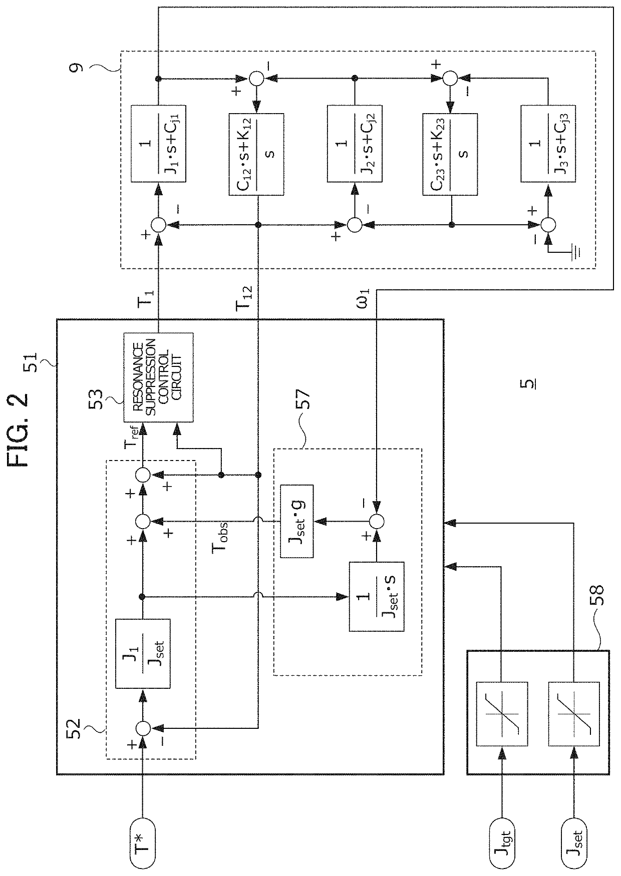
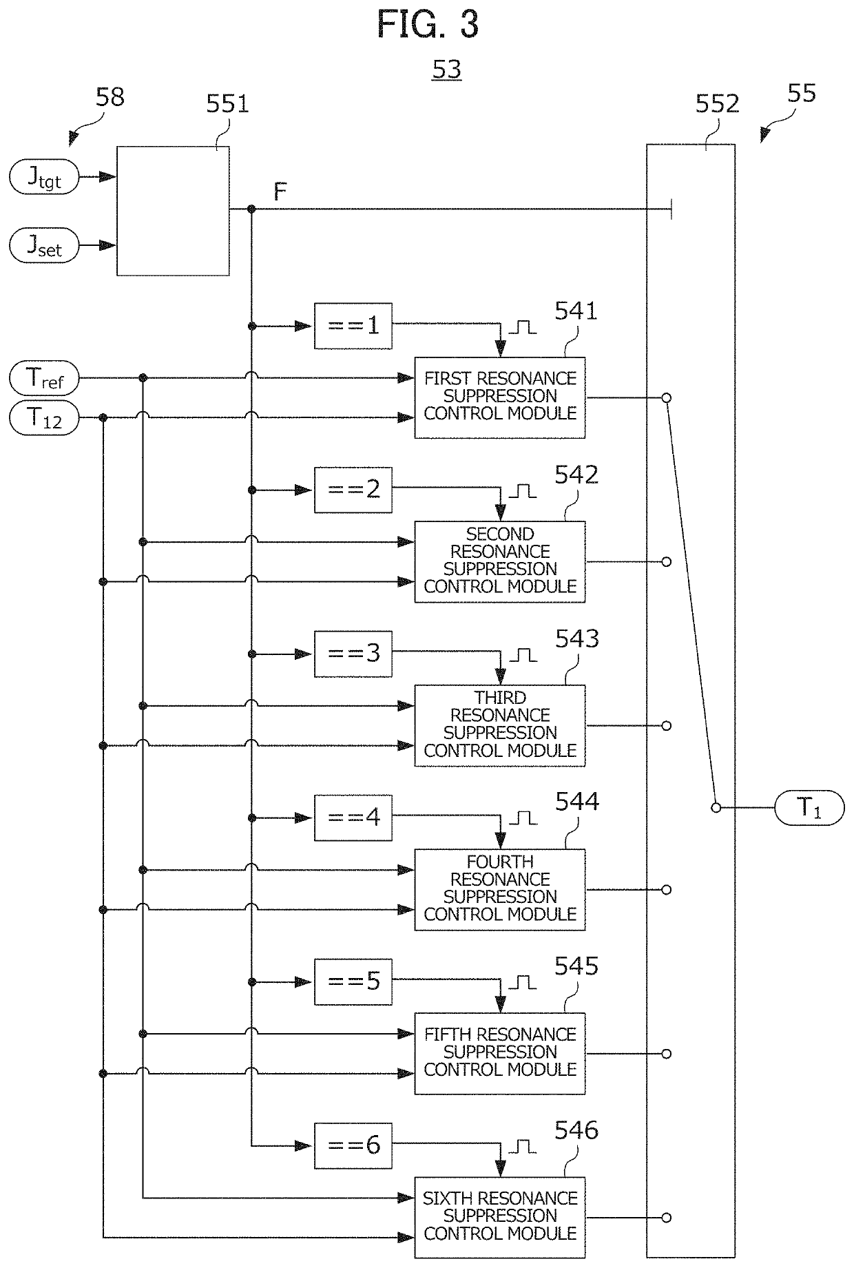
[0038]An embodiment of the present invention will be described in detail below with reference to the drawings. FIG. 1 is a diagram showing the configuration of a dynamometer system S according to the present embodiment. In the dynamometer system S, a drive train of a vehicle including an input shaft Wi and an output shaft Wo connected to the input shaft Wi so as to be able to transmit power is a test piece W, and the performance of the test piece W is evaluated, and the dynamometer system S is referred to as a so-called drive train bench system. In the completed vehicle equipped with the test piece W, a power generating source such as an engine or a drive motor is connected to the input shaft Wi, and drive wheels are connected to the output shaft Wo. Although in the following, a case in which a drive train mounted in a so-called rear wheel drive (FR) vehicle is a test piece W will be described, the present invention is not limited to this case. More specifically, for example, a driv...


PUM


Abstract

According to the present invention, an input-side dynamometer control device is provided with an inertia compensator, a resonance suppression controller 53, a set value acquisition unit 58 for acquiring set values Jset, Jtgt. The resonance suppression controller 53 is provided with: a plurality of resonance suppression control modules 541-546 that generate input-side torque current command signals T1 on the basis of an inertia compensation torque signal Tref and an input-side shaft torque detection signal T12 so as to suppress resonance; and a selector 55 that selects one of the control modules 541-546 on the basis of the set values Jset, Jtgt. The inertia compensation torque signal Tref and the input-side shaft torque detection signal T12 are inputted to one of the resonance suppression control modules selected by the selector 55, and the input-side torque current command signal generated by the selected resonance suppression control module is inputted to an inverter.

Description

TECHNICAL FIELD[0001]The present invention relates to an electric inertia control device. More specifically, the present invention relates to an electric inertia control device which simulates, in a dynamometer system where a dynamometer is connected to the input shaft or the output shaft of a test piece, the behavior of an inertial body having predetermined set inertia by the dynamometer.BACKGROUND ART[0002]Drive train collectively refers to a plurality of devices for transmitting energy generated in an engine to drive wheels, and includes the engine, clutch, transmission, drive shaft, propeller shaft, differential gears, drive wheels, and the like. In a performance evaluation test of a drive train, the transmission actually continues to be driven by the engine, and thus the durability, the quality, and the like thereof are evaluated. In recent years, it has been proposed that a dynamometer system in which a dynamometer is coupled to the output shaft or the input shaft of a drive t...

Claims


Application Information

Patent Timeline
Patent Type & Authority Applications(United States)
IPC IPC(8): G01M13/025
CPCG01M13/025
Inventor YAMAGUCHI, TAKASHI
Owner MEIDENSHA ELECTRIC MFG CO LTD
Why Eureka
Try Eureka