Filter device and filter circuit
- Summary
- Abstract
- Description
- Claims
- Application Information
AI Technical Summary
Benefits of technology
Problems solved by technology
Method used
Image

Examples
first preferred embodiment
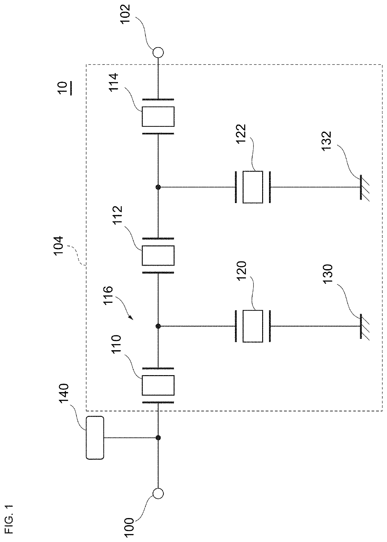
[0027]FIG. 1 is a circuit diagram of a filter device 10 according to a first preferred embodiment of the present invention. The filter device 10 is a filter circuit that allows a signal of a predetermined frequency band to pass therethrough and attenuates signals of the other frequency bands. The filter device 10 is a ladder filter including multiple resonators disposed on a series arm and parallel arms.
[0028]The filter device 10 includes an input terminal 100, an output terminal 102, a filter 104, and an open terminal 140. A signal is input into the input terminal 100 and is output from the output terminal 102.
[0029]The filter 104 includes three series arm resonators 110, 112, and 114, two parallel arm resonators 120 and 122, and two ground terminals 130 and 132. The numbers of series arm resonators, parallel arm resonators, ground terminals, and open terminals are only examples and are not limited thereto.
[0030]Each of the series arm resonators 110, 112, and 114 and the parallel a...
second preferred embodiment
[0052]Other preferred embodiments will be described below by referring to points different from the first preferred embodiment while omitting the same or similar points as the first preferred embodiment. Similar advantages obtained by similar configurations are not repeated in the individual preferred embodiments.
[0053]FIG. 9 is a circuit diagram of a filter device 12 according to a second preferred embodiment of the present invention. In the filter device 12 of the second preferred embodiment, an open terminal 142 is connected to a node between the series arm resonator 110, which is closest to the input terminal 100, and the series arm resonator 112, which is second closest to the input terminal 100. The parallel arm resonator 120 is also connected to this node.
[0054]The electrode forming the open terminal 142 is connected to an open electrode (open portion) provided in or on the multilayer substrate. Heat generated in the series arm resonators 110 and 112, for example, is thus dis...
third preferred embodiment
[0055]FIG. 10 is a circuit diagram of a filter device 15 according to a third preferred embodiment of the present invention. In the filter device 15 of the third preferred embodiment, on a path (first connecting path 166) which connects an input terminal 150 and an output terminal 152, two series arm resonators 160 and 162 and a longitudinally coupled resonator unit 164 are disposed in this order as viewed from the input terminal 150. The longitudinally coupled resonator unit 164 includes three resonators that are each connected to a ground terminal. A resonator 170 is connected to a node between the resonators 160 and 162. The resonator 170 is connected to a ground terminal 172.
[0056]In the third preferred embodiment, an open terminal 174 is connected to a node between the resonators 160 and 162. The electrode defining the open terminal 174 is connected to an open electrode (open portion) provided in or on the multilayer substrate. Heat generated in the resonators 160 and 162 and t...
PUM
 Abstract
Description
Claims
Application Information
 - R&D
- Intellectual Property
- Life Sciences
- Materials
- Tech Scout
- Unparalleled Data Quality
- Higher Quality Content
- 60% Fewer Hallucinations
Browse by: Latest US Patents, China's latest patents, Technical Efficacy Thesaurus, Application Domain, Technology Topic, Popular Technical Reports.
© 2025 PatSnap. All rights reserved.Legal|Privacy policy|Modern Slavery Act Transparency Statement|Sitemap|About US| Contact US: help@patsnap.com