
Resin Line Comprised of a Corrugated Pipe

a technology of corrugated pipes and resin lines, which is applied in the field of resin lines comprised of corrugated pipes, can solve the problems of unsuitable resin lines for longer conveyance stretches of matrix materials, inconvenient use of resin lines, and inability to resist material impressions of corrugated pipes in the matrix material of the component, etc., so as to reduce material consumption and environmental load, and supply matrix materials very efficiently, the effect of reducing the consumption of materials

Active Publication Date: 2021-09-02
FASERVERBUND INNOVATIONS UG HAFTUNGSBESCHRANKT
View PDF0 Cites 0 Cited by
  • Summary
  • Abstract
  • Description
  • Claims
  • Application Information

AI Technical Summary

Benefits of technology

The patent describes a resin line used in a manufacturing process. The resin line has a special shape that allows it to rest on a larger contact surface on the component being manufactured. This makes it easier to position the resin line in the tool and ensures that it doesn't slip or collapse when the material is being conveyed through the tool. The resin line can be easily removed from the finished component without leaving any visible traces. The use of a heat-resistant material, such as polypropylene, helps to prevent the resin line from collapsing even in cases where there is a lot of heat generated during the manufacturing process. Overall, this special shape and material selection improve the manufacturing process and allow for better quality components to be produced.

Problems solved by technology

Such resin lines are unsuitable for longer conveyance stretches of the matrix material in the tool because the matrix material is non-uniformly distributed.
Also, the resin lines with an omega cross section are not particularly load-resistant because, when subjected to pressure, they will widen in the region of the longitudinal slot and then collapse.
In regard to known corrugated pipes, the material impressions of the corrugated pipe in the matrix material of the component have been found to be disadvantageous.
The resin lines with an omega cross section are obtainable only as rod material because they are not flexible enough to be coiled.
Also, it is not possible to lay such resin lines in arcuate courses in a tool.

Method used


Image

  • Resin Line Comprised of a Corrugated Pipe
  • Resin Line Comprised of a Corrugated Pipe

Examples


Embodiment Construction

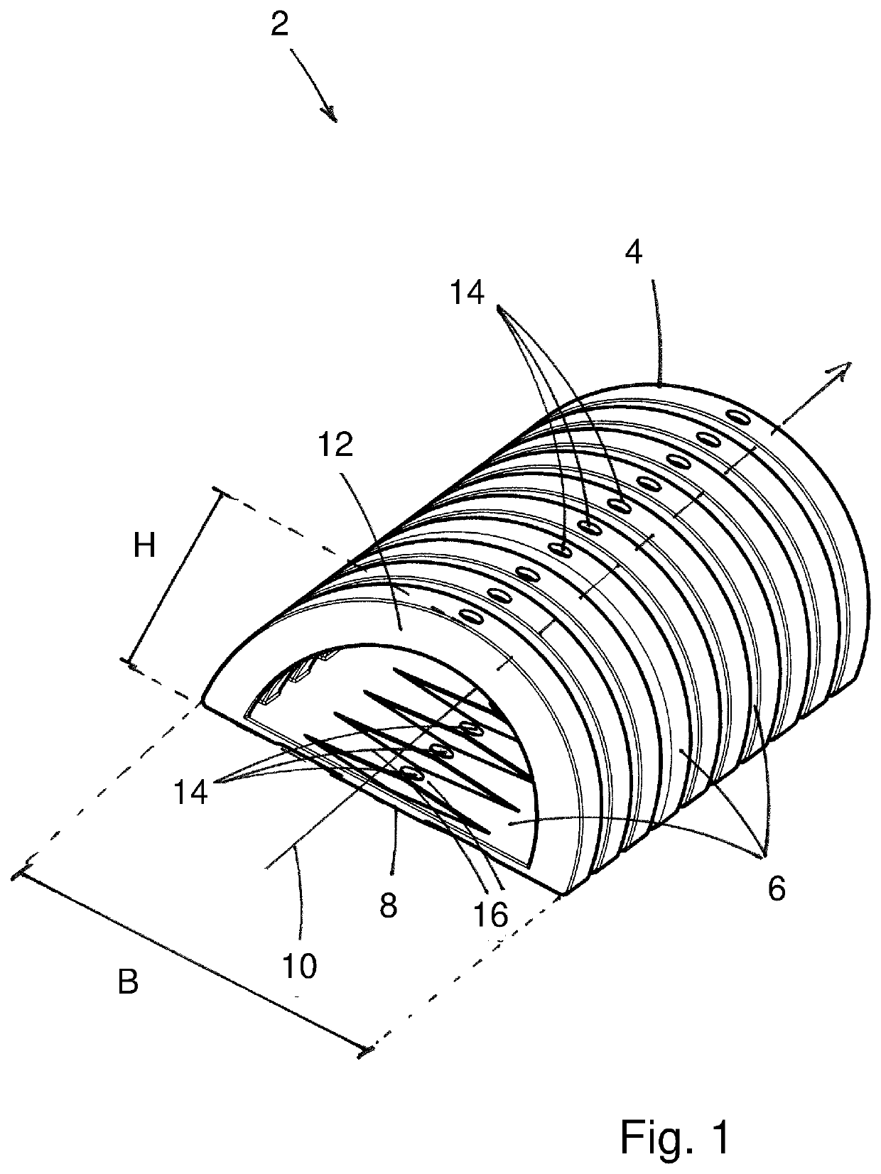
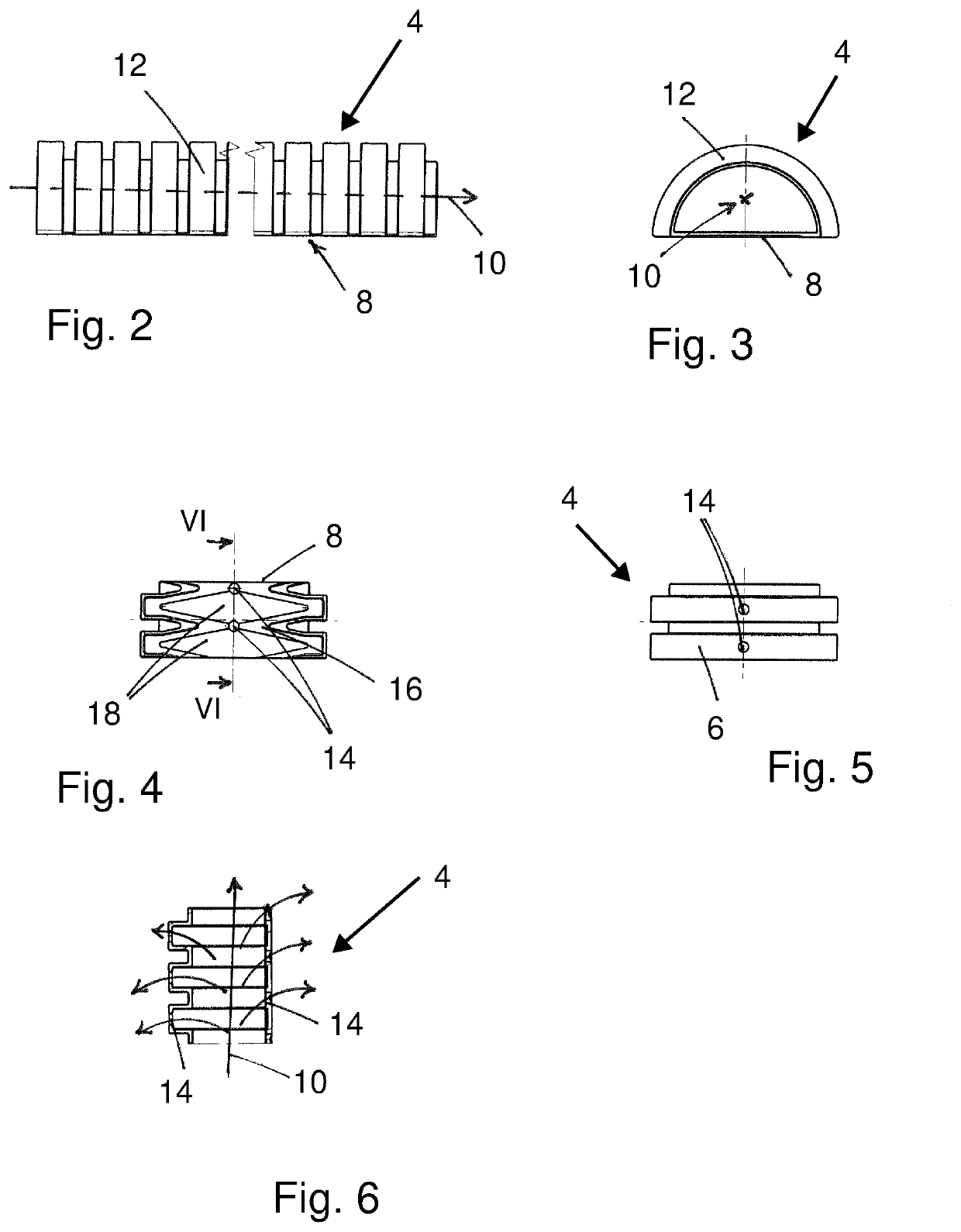
[0030]FIG. 1 shows a section of a resin line 2 that is formed of a corrugated pipe 4. The corrugated pipe 4 comprises a wall of a material that is embodied in corrugations. The corrugations can be rounded in this context or, as shown in the embodiment, can be provided with an angular cross-sectional shape of the corrugation. It is important that the wall 6 is not smooth but, due to a corrugated shape enables bending of the corrugated pipe 4 without this causing kinks in the wall 6 that would obstruct the flow of material and would lead to leakages in the wall 6.

[0031]In the perspective view from above, one can see that the corrugated pipe 4, transverse to the longitudinal center axis 10, has a cross-sectional shape of non-rotational symmetry in that the wall 6 is divided into two parts. In a first part, the wall 6 is provided along the circumference of the wall 6 with a flattened base 8 that extends in a direction transverse to the longitudinal center axis 10 across the length of th...


PUM

PropertyMeasurementUnit
thicknessaaaaaaaaaa
lengthsaaaaaaaaaa
heightaaaaaaaaaa

Abstract

A resin line is provided with a corrugated pipe that has a wall with individual circumferentially arranged through openings. Sections of the wall are circumferentially closed. The wall has a cross-sectional shape of non-rotational symmetry transverse to a longitudinal center axis and is divided in relation to the cross-sectional shape of non-rotational symmetry into a first part and a second part. The first part has a flattened base extending in a transverse direction transverse to the longitudinal center axis across a length of the corrugated pipe. The second part has an arc shape extending in a direction of height transverse to the longitudinal center axis across the length of the corrugated pipe. The flattened base has a width measured in the transverse direction that is larger than a height of the arc shape measured in the direction of height.

Description

BACKGROUND OF THE INVENTION[0001]The invention relates to a resin line comprised of a corrugated pipe with individual through openings arranged in the wall at the circumference.[0002]The vacuum infusion method is disclosed, for example, in DE 102 39 325 B4. For producing a reinforced fiber composite component, the resin line is placed into a tool in order to supply, under vacuum, a liquid matrix material to the reinforcement fibers placed into the tool. The reinforcement fibers can be present as semifinished products in the form of rovings, mats, laid material, webs, multi-axial materials, knit materials, and meshwork, and can be produced from a great variety of fiber materials such as, for example, carbon fibers, glass fibers, aramid fibers, boron fibers or hybrid materials, as well as any combination thereof. The reinforcement fibers are impregnated with the matrix material that is supplied via the resin line. The matrix material fills also the tool mold in this context. As matrix...

Claims


Application Information

Patent Timeline
Patent Type & Authority Applications(United States)
IPC IPC(8): F16L11/15
CPCF16L11/15B29C70/62F16L11/11B29C70/54B29C70/48B29C70/44B29L2023/18B29C70/546B29C70/443
Inventor DIERKES, DOMINIK
Owner FASERVERBUND INNOVATIONS UG HAFTUNGSBESCHRANKT
Learn More