Device and method based on diamond nv centers
a technology device, which is applied in the field of devices and methods of reading the spin state of diamond nv center, can solve the problems that the majority of quantum platforms prevailing today face substantial technical challenges, and achieve the effect of enhancing the performance of hybrid diamond-spintronic devices and efficient optical control
- Summary
- Abstract
- Description
- Claims
- Application Information
AI Technical Summary
Benefits of technology
Problems solved by technology
Method used
Image
Examples
example 1
ng the Spin Readout SNR
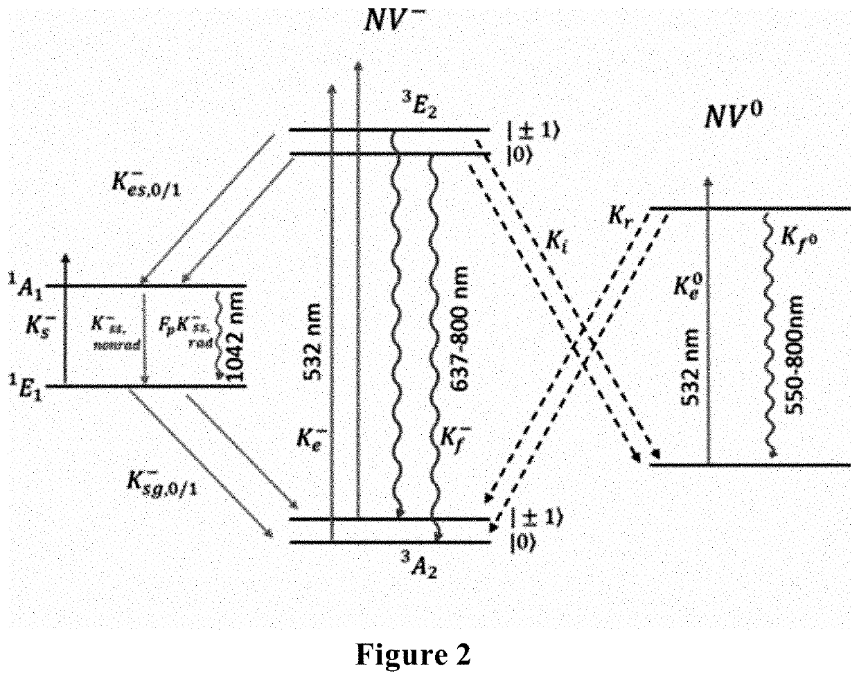
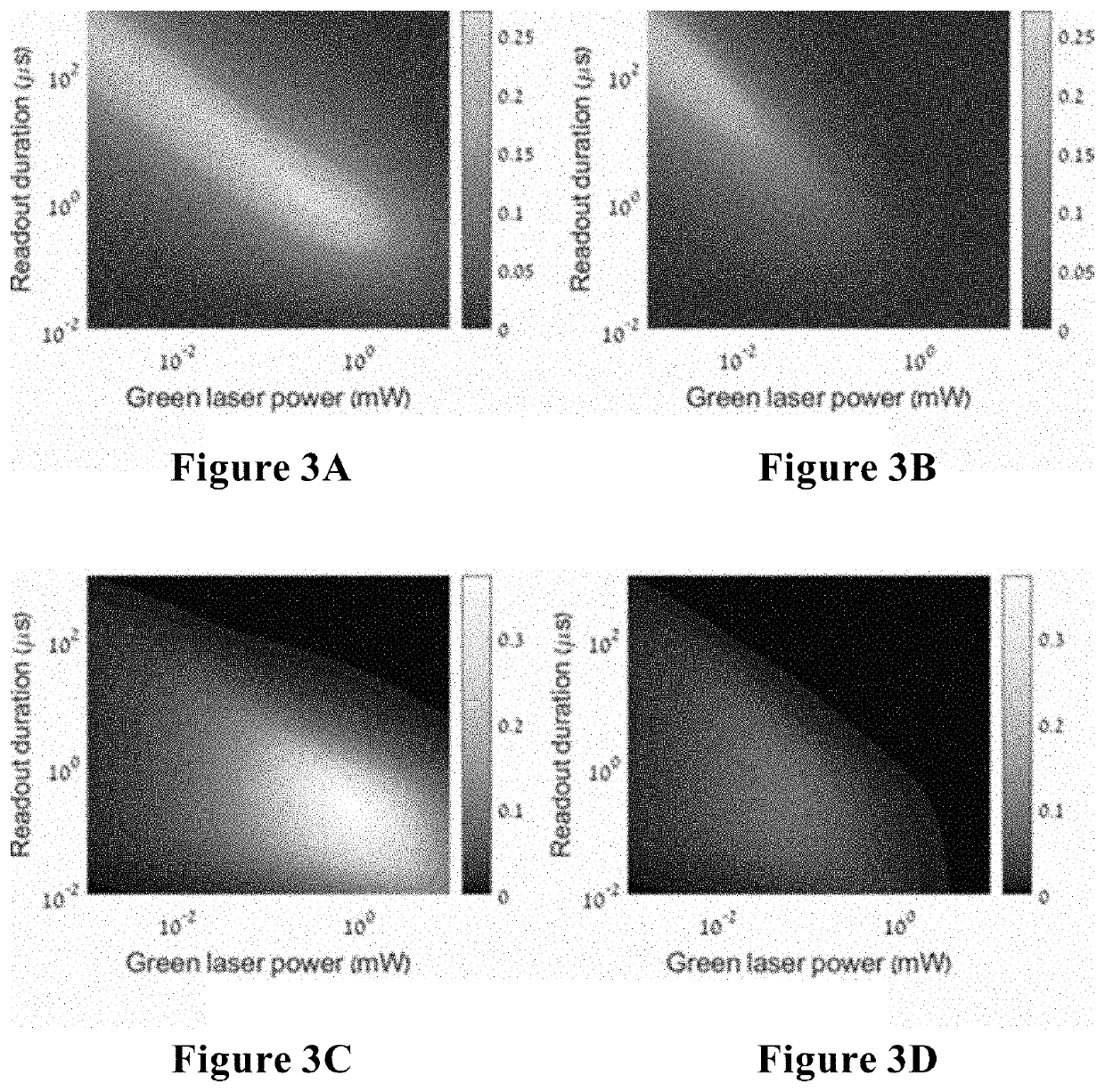
[0107]The negatively charged NV center consists of 2 adjacent lattice sites occupied by a nitrogen atom and a vacancy inside a diamond crystal. The electronic ground state of the NV center is a spin triplet with a 2.87 GHz zero-field splitting between spin projections ms=0 and ms=1. The electronic excited states contain a spin triplet with a strong radiative coupling and a spin singlet with a much weaker radiative coupling. FIG. 2 depicts a simplified energy level diagram of NV− and NV0, together with the main transitions. In red fluorescence-based spin state readout scheme, an NV in the triplet ground state (3A) is excited to the triplet excited state (3E) using green light, and the red fluorescence during the decay back to the ground state is collected. The number of photons collected from each of the spin states dictates the SNR, which is defined as:
SNR=N0-N1N0+N1(1)
where N1 denotes the number of photons collected when the NV is initialized to its ms=|i> st...
example 2
on of IR Fluorescence-Based Spin Readout Scheme
[0111]The pulsed sequence, depicted in FIG. 4A, starts with a short and strong green laser pulse, exciting the NV from the ground state (3A2) to the excited state (3E2) and populating the singlet ground state (1E1) of almost only ms=±1 polarized NVs. Next, a short delay (represented by τ) is introduced to avoid undesired ionization from the excited triplet state, followed by a strong and long 980 nm pulse that excites the NV from the ground singlet state (1E1) to the singlet excited state (1A1) while collecting the emitted 1042-nm fluorescence. Due to the fact that the IR laser does not excite the triplet ground state, no mixing processes are expected, enabling a relatively long measurement. By carefully tuning the green laser pulse power and duration, the sequence can be repeated three times before significant mixing (via the singlet manifold or ionization / recombination processes) takes place, thus enhancing the signal.
[0112]Despite th...
example 3
Improving IR Fluorescence Spin-Readout SNR
[0114]To further improve the spin-readout SNR shown in FIG. 4 while reducing the necessary IR excitation power, overcoming the weak fluorescence signal resulting from the nonradiative nature of the 1A→1E decay is needed. Thus, utilization of optical / plasmonic antennas, hyperbolic metamaterials or a photonic crystal cavity is proposed to strengthen the radiative coupling between the 1A and 1E states and thus increase the singlet fluorescence signal.
[0115]Photonic crystal structures with small mode volumes (V≈(λ / n)3) and high-quality factors (high frequency-to-bandwidth ratio in the resonator) are now within reach, and together with the relatively narrow IR fluorescence spectral width, are expected to provide high Purcell factors, especially for nano-diamonds and diamond films, but also potentially for bulk diamonds.
[0116]The Purcell factor, an enhancement of the spontaneous emission rate from the excited state due to radiative coupling, depen...
PUM
 Abstract
Description
Claims
Application Information
 - R&D Engineer
- R&D Manager
- IP Professional
- Industry Leading Data Capabilities
- Powerful AI technology
- Patent DNA Extraction
Browse by: Latest US Patents, China's latest patents, Technical Efficacy Thesaurus, Application Domain, Technology Topic, Popular Technical Reports.
© 2024 PatSnap. All rights reserved.Legal|Privacy policy|Modern Slavery Act Transparency Statement|Sitemap|About US| Contact US: help@patsnap.com


