
Roller wrench

a technology of roller wrenches and rollers, applied in the field of roller wrenches, can solve the problems of inability to effectively position the roller wrenches in their positions, and achieve the effect of reliable positioning function and effective positioning of the roller wrench

Active Publication Date: 2021-08-26
KABO TOOL COMPANY
View PDF0 Cites 0 Cited by
  • Summary
  • Abstract
  • Description
  • Claims
  • Application Information

AI Technical Summary

Benefits of technology

The invention is a roller wrench that solves the problem of difficulty in positioning rollers and a reversing knob. It is designed to provide reliable positioning function and effectively position the rollers and reversing knob in their positions. It is easy to manufacture and reduce manufacturing costs.

Problems solved by technology

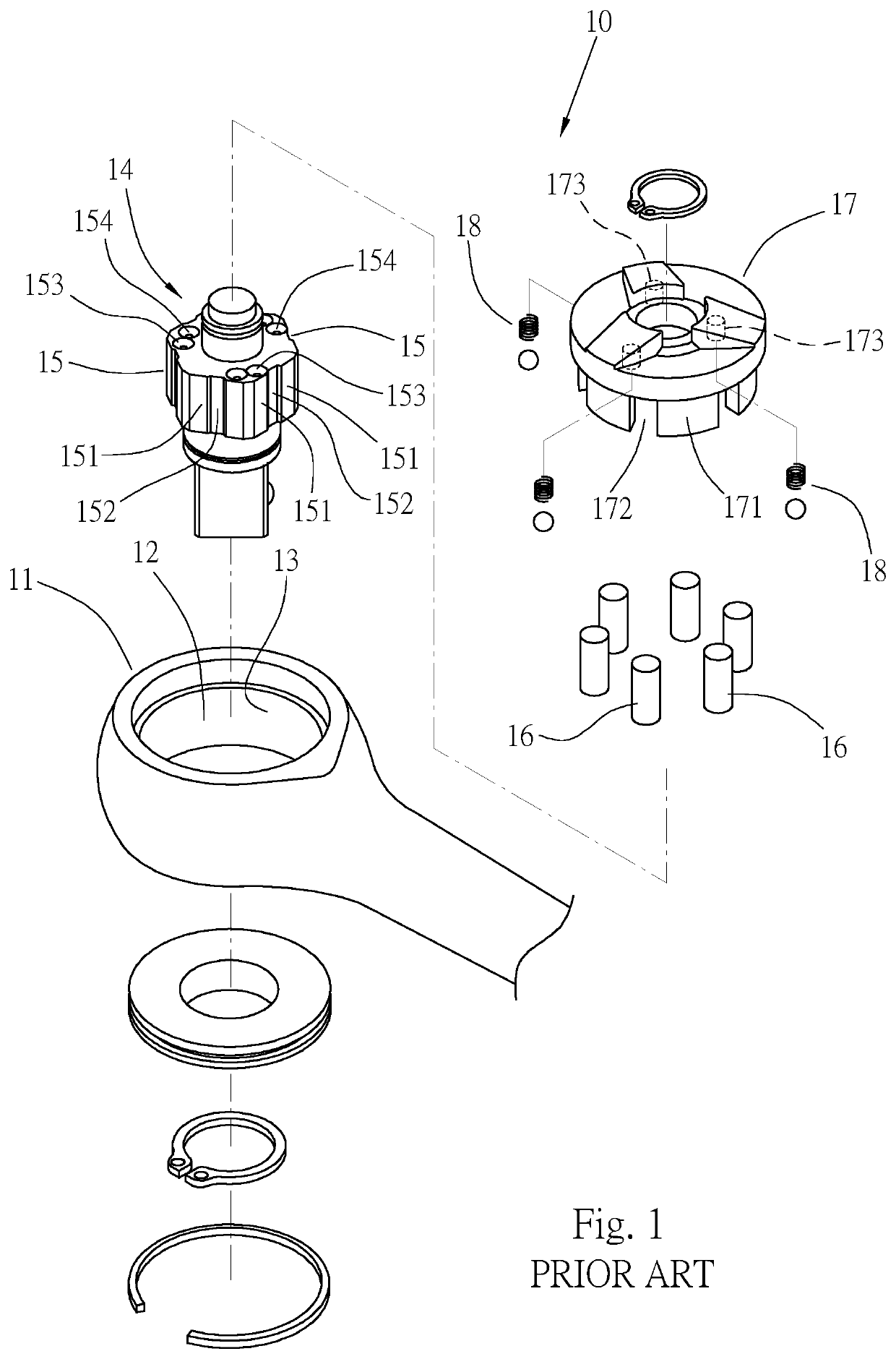
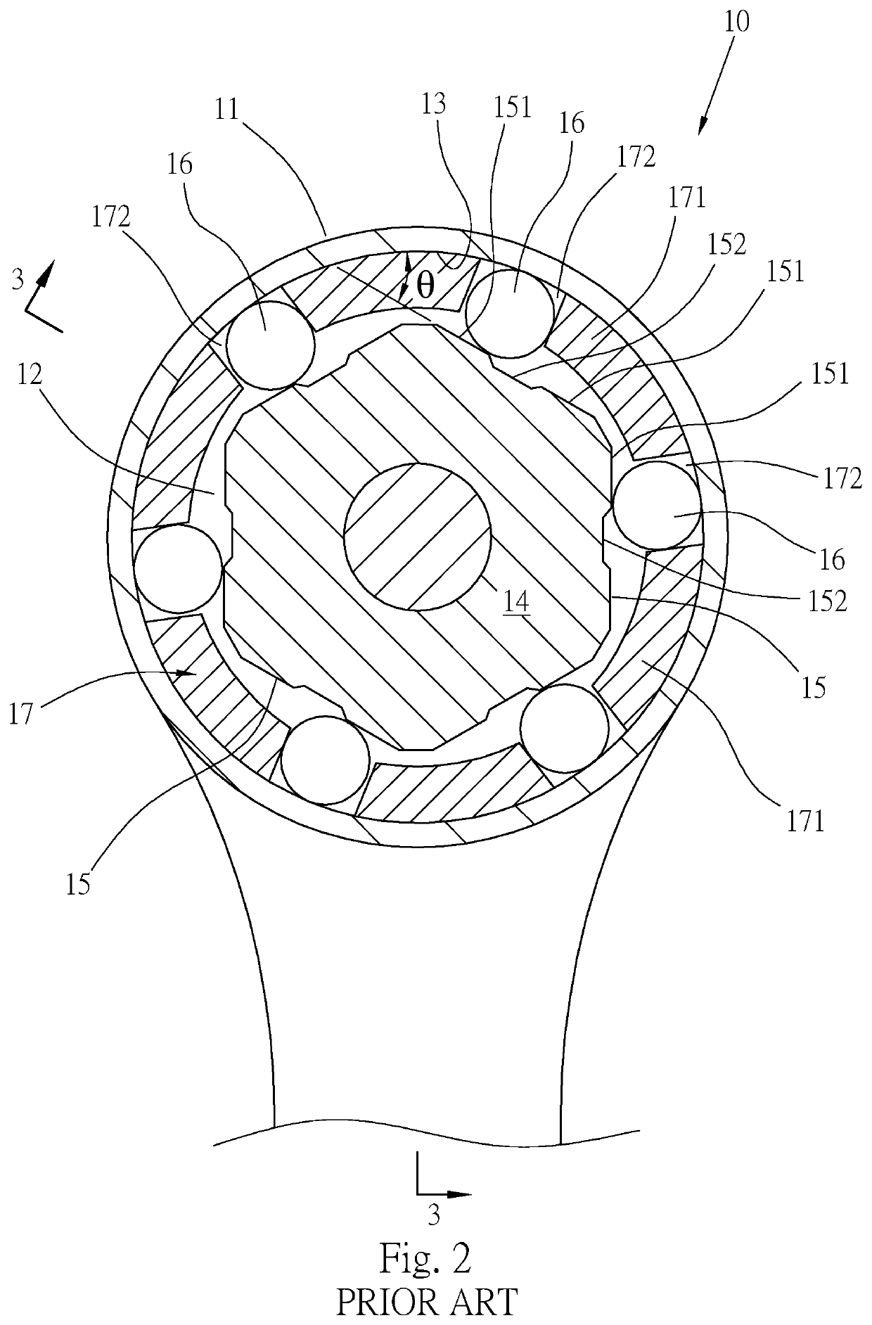
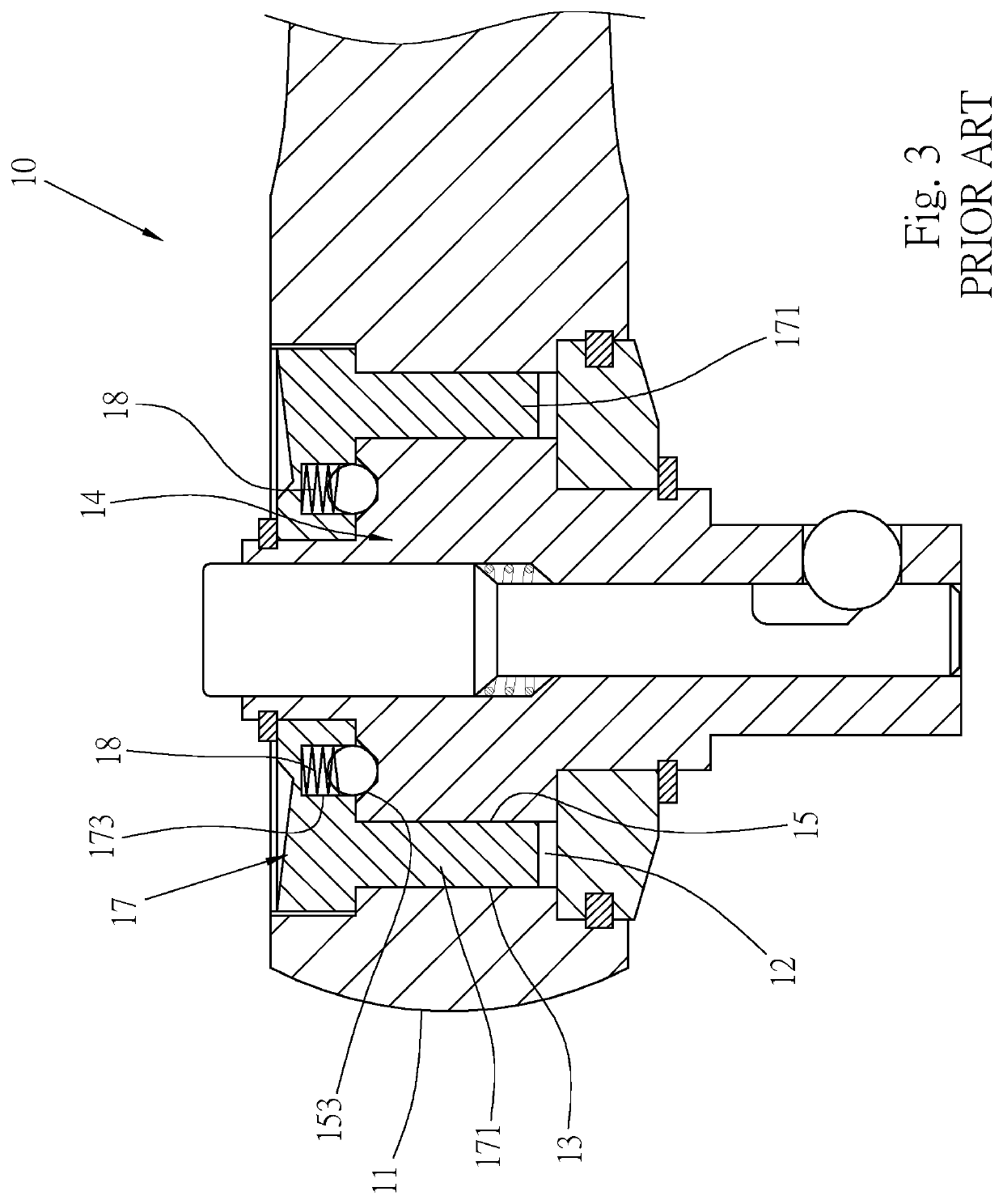
Furthermore, due to the limitation of the disposing locations, the positioning holes 153, 154 have small hole diameter and shallow depth, which makes it easy for the elastic positioning components 18 to slide out of the positioning holes 153, 154, such uncertain and unreliable positioning will result in the rollers 16 being unable to be effectively positioned in their positions.

Method used


Image

  • Roller wrench
  • Roller wrench
  • Roller wrench

Examples


Embodiment Construction

[0037]Please refer to FIGS. 4 to 6 for a roller wrench 20 of a first preferred embodiment of the invention, the roller wrench 20 comprises: a body 30, a driving member 40, a plurality of rollers 50, a reversing knob 60 and at least one elastic positioning component 70.

[0038]The body 30 has a head 31 and a shaft 36 connected to each other, and the head 31 is located at a front end of the shaft 36. A top surface of the head 31 is inwardly recessed with a circular chamber 32; and a bottom surface of the head 31 is penetrated, such as by disposing with a through hole 34.

[0039]Please refer to FIG. 7 in conjunction with the above figures. The driving member 40 is a regular polygonal component, such as a regular quadrilateral, a regular pentagon, a regular hexagon, a regular octagon, etc., and has a plurality of sides. In the preferred embodiment disclosed in this specification, the driving member 40 is a regular hexagonal component as an example, and has six sides 41. Each of the sides 41...


PUM


Abstract

The invention relates to a roller wrench comprising: a body with a circular chamber; a driving member being a regular polygonal component capable of rotating in the chamber; a plurality of rollers installed in the chamber, each of the rollers is located between a side of the driving member and a peripheral wall of the chamber; a reversing knob capable of driving the rollers to move in the chamber so that each of the rollers moves between two edges of each of sides of the driving member; and at least one elastic positioning component installed on one of the sides of the driving member, and capable of elastically moving into the driving member or protruding from a peripheral surface of the driving member; the elastic positioning component is moved into the driving member when being compressed; and is protruded from the driving member when not being acted on by an external force; and each of the elastic positioning components limits one of the rollers, thereby positioning the rollers and the reversing knob.

Description

CROSS REFERENCE TO RELATED APPLICATION[0001]This patent application claims priority to U.S. Provisional Patent Application Ser. No. 62 / 981,322, entitled “ROLLER WRENCH”, filed on Feb. 25, 2020, and priority to U.S. Provisional Patent Application Ser. No. 63 / 003,775, entitled “ROLLER WRENCH”, filed on Apr. 1, 2020.BACKGROUND OF THE INVENTIONField of Invention[0002]The invention is related to wrenches, and more particularly to a roller wrench.Related Art[0003]FIG. 1 shows a conventional reversible roller wrench 10, a driving member 14 is installed in a circular chamber 12 of a head 11, the driving member 14 has six sides 15, a center of each of the sides 15 has a concave portion 152, and the concave portion 152 makes two edges of each of the sides 15 respectively form a latching surface 151. Six rollers 16 are installed between the six sides 15 and a peripheral wall 13 of the chamber 12 respectively. A reversing knob 17 is installed on a top of the head 11, and six walls 171 are protr...

Claims


Application Information

Patent Timeline
Patent Type & Authority Applications(United States)
IPC IPC(8): B25B13/46F16D71/04
CPCB25B13/463F16D71/04B25B13/461B25B13/462
Inventor HSIEH, CHIH-CHING
Owner KABO TOOL COMPANY
Learn More