
Light detection system, discharge probability calculating method, and received light quantity measuring method

a technology of light detection system and probability calculation, applied in the field of light detection system, can solve problems such as failure detection error, above-mentioned problems, not only in the flame detection system, but also in the light detection field

Active Publication Date: 2021-08-19
YAMATAKE HONEYWELL CO LTD
View PDF0 Cites 1 Cited by
  • Summary
  • Abstract
  • Description
  • Claims
  • Application Information

AI Technical Summary

Benefits of technology

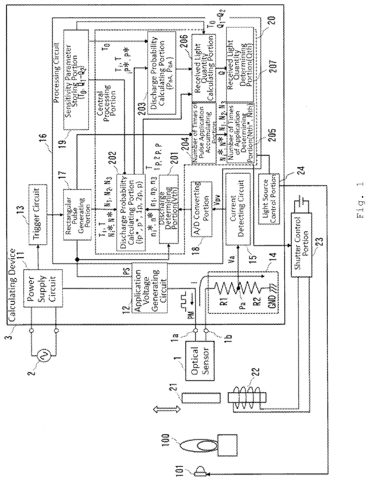
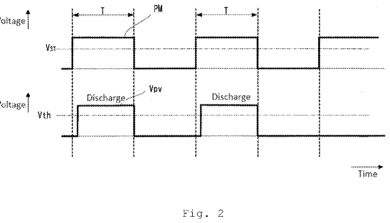
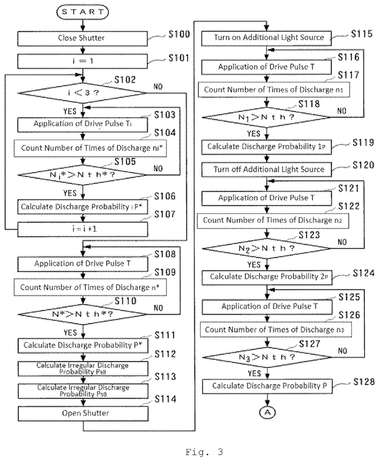
This patent describes a system and method for measuring the amount of light that is received. It is capable of calculating the amount of light even when there is uncertainty in the way in which the light is produced. This method helps to accurately detect the presence of flames and reduces the risk of incorrect sensor readings. Additionally, the patent describes a way to improve the detection of irregular discharges that occur without being affected by the pulse width of the driving voltage.

Problems solved by technology

However, the discharge of the actual optical sensor includes an irregular discharge caused by a noise, which is generally referred to as a failure, and thus there is a case where the discharge occurs even when light generated by the flame does not exist and causes erroneous detection.
However, in the failure detecting device disclosed in PTL 3, there is no discriminating method for distinguishing between the regular discharge and the irregular discharge with the change in measurement sensitivity due to the life of the optical sensor, and thus there is a possibility of erroneous detection of the failure.
It should be noted that the above problems occur not only in the flame detection system but also in the light detection system using the optical sensor.

Method used


Image

  • Light detection system, discharge probability calculating method, and received light quantity measuring method
  • Light detection system, discharge probability calculating method, and received light quantity measuring method
  • Light detection system, discharge probability calculating method, and received light quantity measuring method

Examples


embodiment

[0035]Hereinafter, a method of measuring an irregular discharge caused by a noise component and a method of measuring a received light quantity will be described. An optical sensor using a photoelectric effect is a photoelectric tube, which is energized by a photon hitting an electrode. The energization proceeds under the following conditions.

[Operation of Optical Sensor]

[0036]When a photon hits one of the electrodes in a state in which a voltage is applied between a pair of electrodes of an optical sensor, photoelectrons are emitted at a certain probability, and an electron avalanche of electrons is produced to cause energization (a discharge current flows between the electrodes).

[0037]While a voltage is applied between the electrodes, the optical sensor continues to be energized. Alternatively, when the energization of the optical sensor is confirmed, the voltage is lowered immediately, so that the energization is stopped. As described above, when the voltage between the electrode...


PUM


Abstract

To calculate a probability of an optical sensor's irregular discharge, a light detection system includes an optical sensor, an application voltage generating circuit that applies a drive pulse voltage to the optical sensor, a discharge determining portion that detects the optical sensor's discharge, a discharge probability calculating portion that calculates a discharge probability for each of first and second states in which the optical sensor is shielded from light and the drive pulse voltage's width in the second state is different from the first state, a sensitivity parameter storing portion storing the drive pulse voltage's reference pulse width as the optical sensor's sensitivity parameter, and another discharge probability calculating portion that calculates an irregular discharge's probability that occurs without depending on the optical sensor's received light quantity, based on the sensitivity parameter, and the discharge probabilities calculated and the drive pulse voltage's widths in the first and second states.

Description

CROSS REFERENCE TO RELATED APPLICATIONS[0001]This patent application claims the benefit of foreign priority to Japanese Patent Application No. JP 2020-025481 filed on Feb. 18, 2020, the disclosure of which is hereby incorporated by reference in its entirety.BACKGROUND OF THE INVENTION[0002]The present disclosure relates to a light detection system configured to detect light such as a flame.[0003]As an optical sensor configured to detect the presence or absence of a flame based on ultraviolet rays emitted from light of the flame in a combustion furnace or the like, a photoelectric tube type ultraviolet sensor may be used. It has been observed that an irregular discharge phenomenon (pseudo discharge) caused by a noise component other than a discharge occurring due to a photoelectric effect occurs in discharge of the photoelectric tube type ultraviolet sensor.[0004]PTL 1 proposes a flame detection system in which a pulse width of a drive pulse to be applied to an optical sensor is cont...

Claims


Application Information

Patent Timeline
Patent Type & Authority Applications(United States)
IPC IPC(8): G01J1/42G01J1/02
CPCG01J1/4209G01J2001/444G01J1/0228G01J1/0266G01J5/30G01J5/0018G06F17/18G01J1/044G01J1/10G01J1/429G01J1/44H01J40/14G01J2001/4446
Inventor ONUMA, SHUNMORI, RAITA
Owner YAMATAKE HONEYWELL CO LTD
Learn More