Operational amplifier
a technology of operation amplifier and output stage, which is applied in the direction of differential amplifier, amplifier details, and amplifier with semiconductor devices/discharge tubes, etc., can solve the problems of voltage fluctuation that occurs in the output stage of the conventional operation amplifier, and the short current is reduced, so as to suppress the voltage fluctuation in the output stage. , the effect of short curren
- Summary
- Abstract
- Description
- Claims
- Application Information
AI Technical Summary
Benefits of technology
Problems solved by technology
Method used
Image
Examples
first embodiment
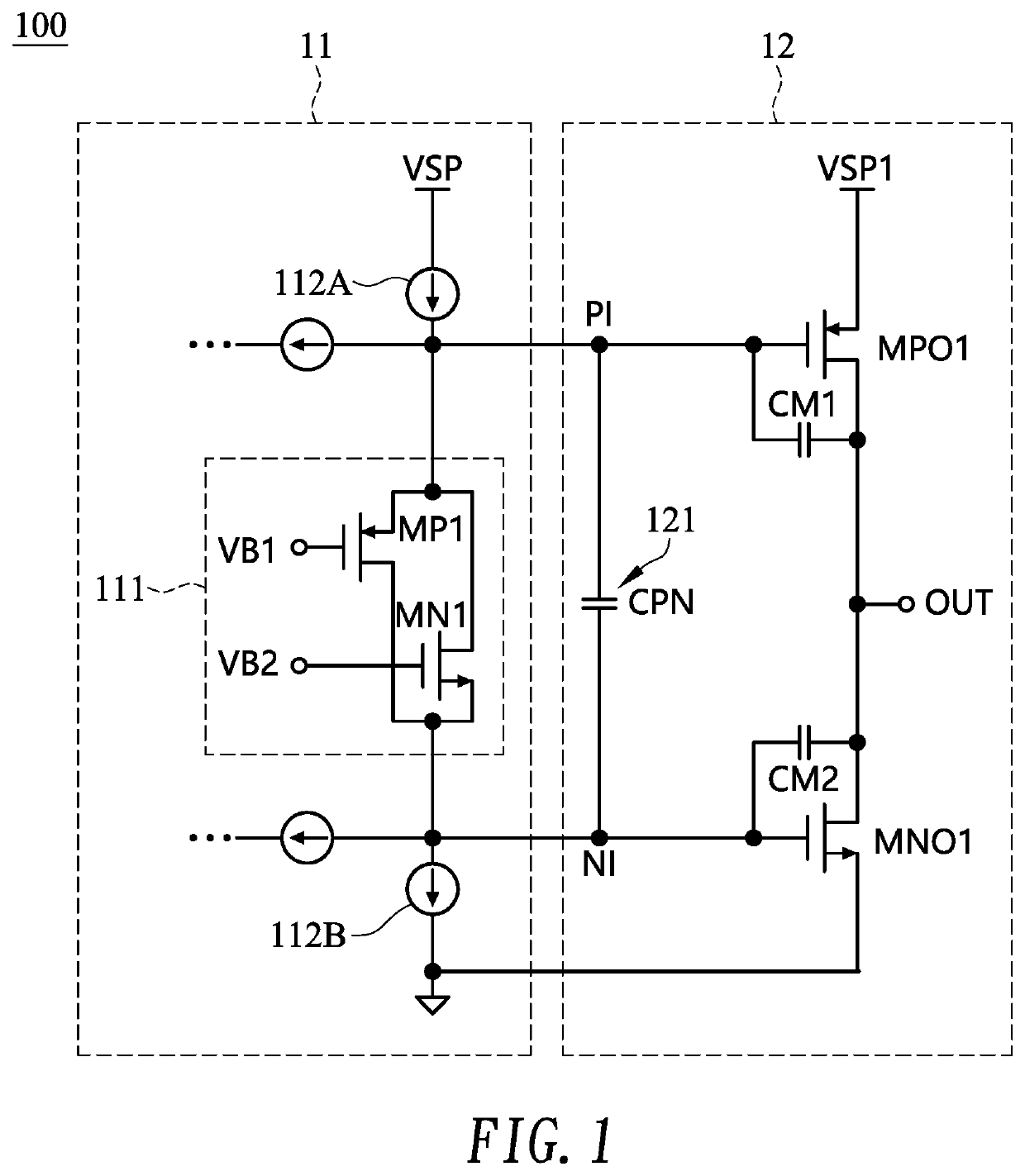
[0010]FIG. 1 shows a circuit diagram illustrating an operational amplifier 100 according to the present invention, adaptable to, but not necessarily, a source driver of a flat panel display such as a liquid crystal display (LCD). The operational amplifier 100 of the embodiment may primarily include a floating current input stage 11 and an output stage 12.
[0011]In the embodiment, the output stage 12 may include a first output transistor MPO1 (e.g., p-channel metal-oxide-semiconductor field-effect transistor (PMOS)) and a second output transistor MNO1 (e.g., n-channel metal-oxide-semiconductor field-effect transistor (NMOS)) connected in series between two power nodes such as a positive supply voltage VSP1 and a ground. Therefore, the operational amplifier may operate in positive power range. Alternatively, in the present embodiment and the following embodiments, the two power nodes may be the ground and a negative supply voltage. Therefore, the operational amplifier may operate in ne...
second embodiment
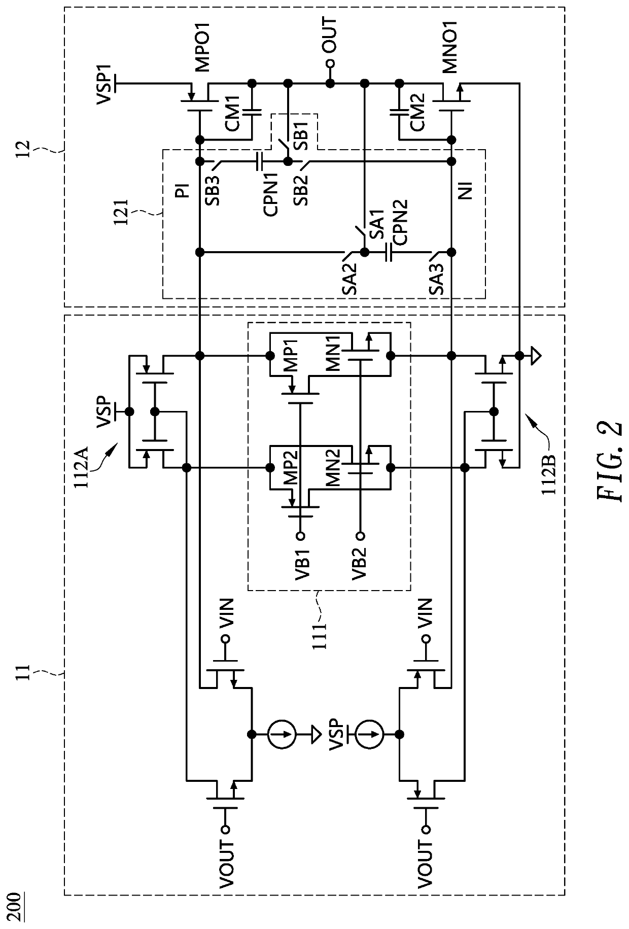
[0016]FIG. 2 shows a circuit diagram illustrating an operational amplifier 200 according to the present invention. The operational amplifier 200 of FIG. 2 is similar to the operational amplifier 100 of FIG. 1 with the following exceptions.
[0017]In the embodiment, the decoupling capacitor circuit 121 may include a first decoupling capacitor CPN1 and a second decoupling capacitor CPN2, which are switchably connected in parallel between the first drive node PI and the second drive node NI. Specifically, a first end of the first decoupling capacitor CPN1 is electrically connected to the output node OUT via an (optional) first switch SB1, and to the second drive node NI via a second switch SB2; and a second end of the first decoupling capacitor CPN1 is electrically connected to the first drive node PI via a third switch SB3. A first end of the second decoupling capacitor CPN2 is electrically connected to the output node OUT via an (optional) fourth switch SA1, and to the first drive node...
third embodiment
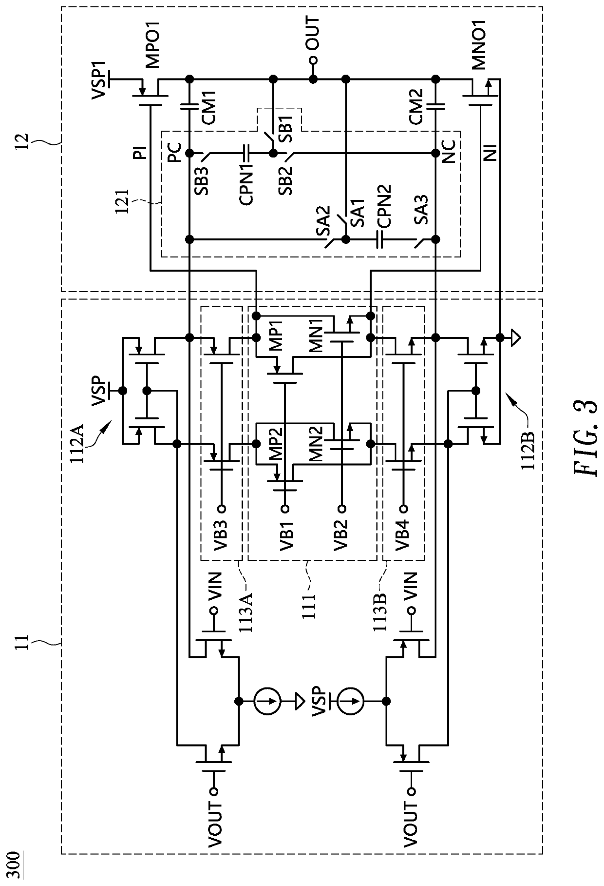
[0019]FIG. 3 shows a circuit diagram illustrating an operational amplifier 300 according to the present invention. The operational amplifier 300 of FIG. 3 is similar to the operational amplifier 200 of FIG. 2 with the following exceptions.
[0020]In the embodiment, the first Miller capacitor CM1 is electrically connected between a first connect node PC (instead of the first drive node PI) and the output node OUT, and the second Miller capacitor CM2 is electrically connected between a second connect node NC (instead of the second drive node NI) and the output node OUT. The decoupling capacitor circuit 121 is electrically connected between the first connect node PC and the second connect node NC (instead of between the first drive node PI and the second drive node NI).
[0021]In the embodiment, the floating current input stage 11 may further include a first cascade circuit 113A (composed of two transistors (e.g., PMOSs) connected in parallel with their gates coupled together) electrically...
PUM
 Abstract
Description
Claims
Application Information
 - R&D
- Intellectual Property
- Life Sciences
- Materials
- Tech Scout
- Unparalleled Data Quality
- Higher Quality Content
- 60% Fewer Hallucinations
Browse by: Latest US Patents, China's latest patents, Technical Efficacy Thesaurus, Application Domain, Technology Topic, Popular Technical Reports.
© 2025 PatSnap. All rights reserved.Legal|Privacy policy|Modern Slavery Act Transparency Statement|Sitemap|About US| Contact US: help@patsnap.com


