Structural member with stabilizing protrusions

a structural member and protruding technology, applied in the direction of sheet joining, fastening means, storage devices, etc., can solve the problems of inconvenient and not cost-effective horizontal beam fitting, inconvenient and proper assembly, and inconvenient construction of horizontal beams, so as to achieve tighter connection

Active Publication Date: 2021-08-12
FRAZIER INDAL
View PDF0 Cites 0 Cited by
  • Summary
  • Abstract
  • Description
  • Claims
  • Application Information

AI Technical Summary

Benefits of technology

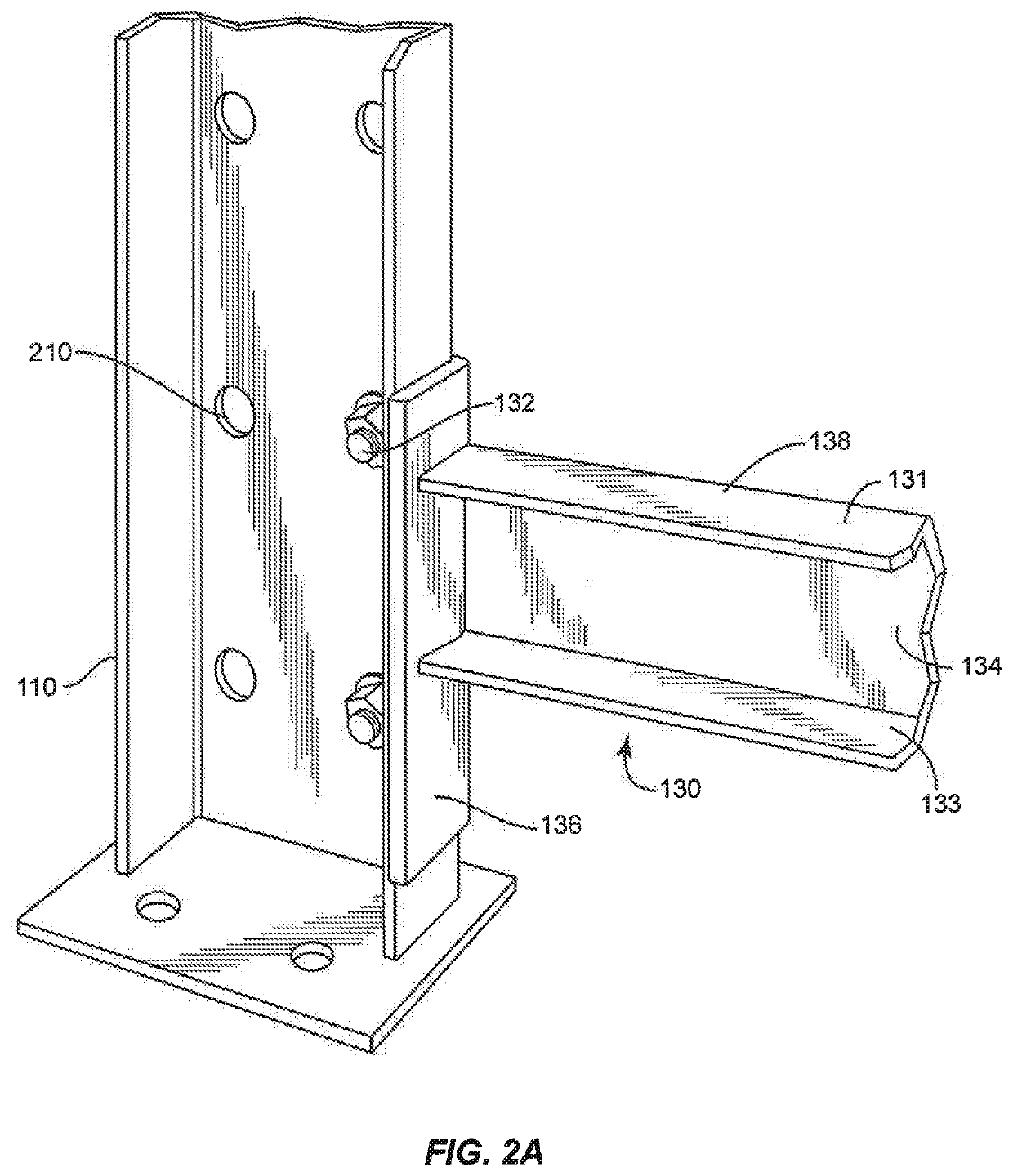
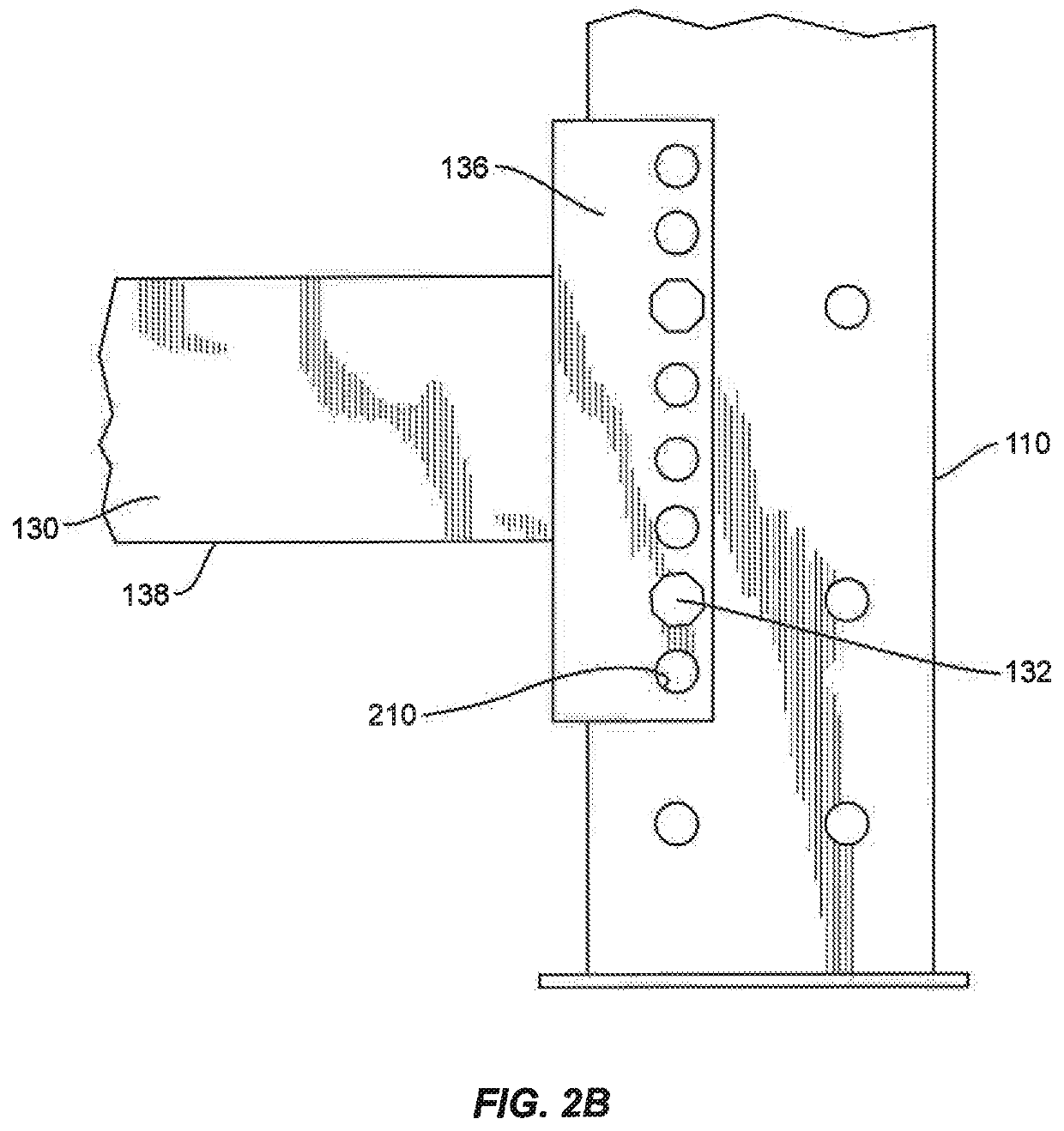
[0010]An inside surface of the first arm, which faces the vertical column, can include a plurality of protrusions (projections). The protrusions can be formed by pressing dimples from the outside surface of the first arm. The protrusions improve the contacting fit between the inside surface of the first arm and the vertical column, which can be about 1 / 16 to ¼ inches apart, more commonly about 2 / 16 to 4 / 16 inches, most commonly about 2 / 16 to 3 / 36 inches. The second arm of the connection bracket can have pre-formed bolt receiving holes that overlap corresponding bolt receiving holes on the vertical column. This arm is bolted to and typically lays flat against the vertical column. In another embodiment of the invention, the preformed holes on the connection bracket can be on the first arm, which faces the vertical column, with the protrusions on the second arm. In another embodiment of the invention, the holes and protrusions can be on both the first and second arms.
[0012]In another embodiment of the invention, a flap protrusion, such as in the shape of a pie-shaped wedge can be formed by pressing into the first arm with enough force to separate a portion of the dimple from the first arm, to leave a gap. This will permit the open end of the dimple to bend back towards the first arm when the connection bolt is tightened and the inside surface of the connection bracket is pressed against the vertical column, making for an even tighter connection.

Problems solved by technology

Therefore, the racks often need to be strong enough to support thousands of pounds and can be high off the ground, making proper, tight assembly both important and difficult.
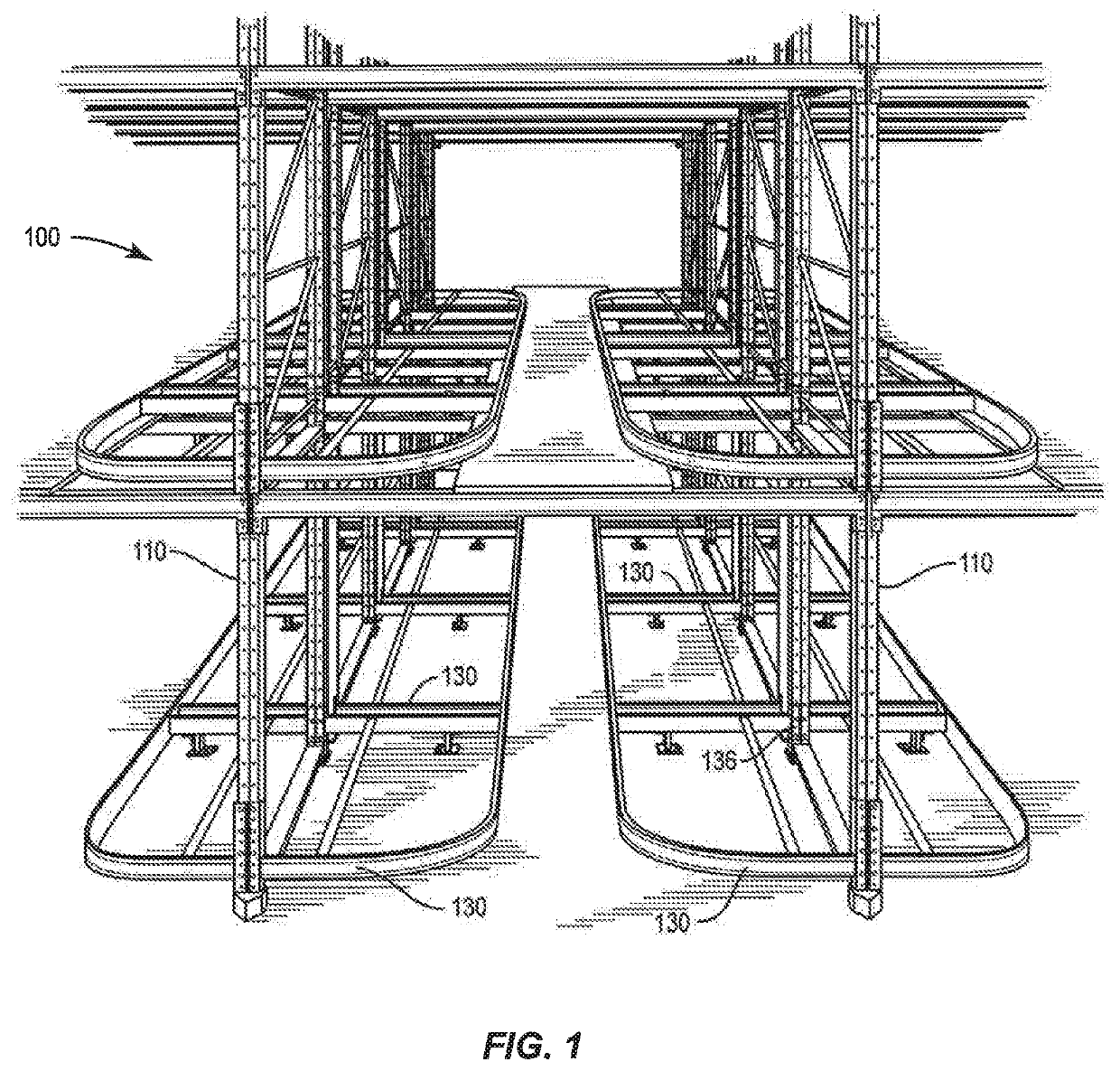
Therefore, it is inconvenient and not cost effective to form horizontal beam 130 with clean, precise corners and highly precise dimensions.
However, these gaps can lead to imprecise fitting of the final construction.
The excessive wobble and sway of loosely fitting parts can unsatisfactorily decrease the strength, stability and durability of storage rack 100.

Method used


Image

  • Structural member with stabilizing protrusions
  • Structural member with stabilizing protrusions
  • Structural member with stabilizing protrusions

Examples


Embodiment Construction

[0021]The present disclosure may be understood more readily by reference to the following detailed description of the disclosure taken in connection with the accompanying figures, which form a part of this disclosure. It is to be understood that this disclosure is not limited to the specific devices, methods, conditions or parameters described and / or shown herein, and that the terminology used herein is for the purpose of describing particular embodiments by way of example only and is not intended to be limiting of the claimed disclosure.

[0022]Also, as used in the specification and including the appended claims, the singular forms “a,”“an,” and “the” include the plural, and reference to a particular numerical value includes at least that particular value, unless the context clearly dictates otherwise. Ranges may be expressed herein as from “about” or “approximately” one particular value and / or to “about” or “approximately” another particular value. When such a range is expressed, an...


PUM


Abstract

A horizontal support beam is provided with a vertical connection bracket, constructed to attach the horizontal beam to a vertical column of a storage rack system. The vertical connection bracket includes a plurality of protrusions positioned to eliminate some of the gaps that can exist between the bracket and column. The vertical connection bracket can be an L shaped angle bracket. An inside surface of the first arm can include a plurality of protrusions, which can be formed by pressing dimples into the first arm, to help ensure a tight, contacting fit between the inside surface of the first arm and the vertical column.

Description

CROSS REFERENCE TO RELATED APPLICATIONS[0001]This application claims priority as a continuation of U.S. application Ser. No. 16 / 783,470, filed Feb. 6, 2019, the contents of which are incorporated herein by reference, in their entirety.BACKGROUND OF THE INVENTION[0002]The invention relates generally to storage racks and more particularly to a support member for a storage rack system for industrial warehouse uses and the like.[0003]Storage racks are commonly used to hold goods, which are often loaded onto pallets. The racks are often four, five or more levels high. The loaded pallets often weigh 2000-3000 pounds. Therefore, the racks often need to be strong enough to support thousands of pounds and can be high off the ground, making proper, tight assembly both important and difficult. An example of a fully assembled storage rack system 100 is shown generally in FIG. 1.[0004]Storage rack 100 includes a plurality of vertical columns 110 extending vertically upward from the floor, ground...

Claims


Application Information

Patent Timeline
Patent Type & Authority Applications(United States)
IPC IPC(8): B65G1/04B65G1/02F16B12/40
CPCB65G1/04F16B12/40B65G1/02F16B5/08
Inventor IELLIMO, DOMENICK
Owner FRAZIER INDAL
Why Eureka
Try Eureka