An adjustable steam turbine wheel inner hole grinding device

A technology for grinding devices and steam turbines, which is applied in the direction of grinding devices, grinding machine tools, and parts of grinding machine tools. It can solve the problems of affecting maintenance frequency and equipment life, labor consumption, and increasing maintenance frequency, etc., so as to avoid poor grinding surface. Influence, benefit, manufacture and installation, and the effect of optimizing the stress situation

Inactive Publication Date: 2016-08-10
DATANG ANYANG POWER GENERATION PLANT
View PDF7 Cites 0 Cited by
  • Summary
  • Abstract
  • Description
  • Claims
  • Application Information

AI Technical Summary

Problems solved by technology

[0002] The steam turbine is the core and main equipment of the power generation enterprise. The maintenance frequency and service life of the steam turbine have a great influence on the operating rate and power generation cost of the power generation enterprise. During the maintenance process of the steam turbine, it is often necessary to install the opposite wheel. The accuracy of this installation is very high. Small errors and mismatches will also have a great impact on the working status of the steam turbine, which will eventually affect the maintenance frequency and equipment life, resulting in an increase in the cost of the enterprise. In order to overcome this problem, it is usually necessary to align the holes when installing the wheels The inner wall is ground to ensure the accuracy of the installation. This kind of grinding work was basically done by hand in the past. There are many defects in this grinding method. Secondary scratches are caused to the grinding surface. After installation and use, the operation coordination cannot reach the optimal state, which affects the single operation time and increases the frequency of maintenance. There are certain requirements for the quality and skills of personnel

Method used


Image

  • An adjustable steam turbine wheel inner hole grinding device
  • An adjustable steam turbine wheel inner hole grinding device
  • An adjustable steam turbine wheel inner hole grinding device

Examples


Embodiment Construction

[0010] In order to fully explain the implementation of the present invention, examples of the implementation of the present invention are provided. These implementation examples are merely illustrative of the present invention and do not limit the scope of the present invention.

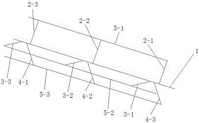
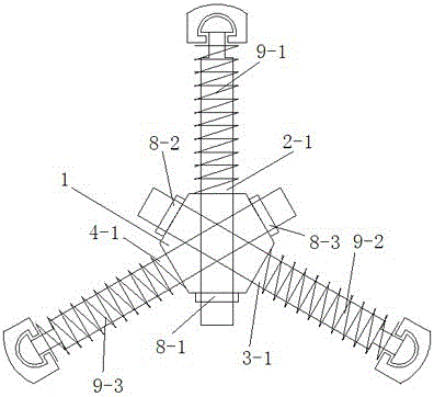
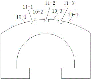
[0011] As attached figure 1 , Attached figure 2 , Attached image 3 , Attached Figure 4 As shown, an adjustable steam turbine wheel inner hole grinding device includes a main shaft 1. The main shaft 1 is connected to a rotating drive device. At least two rows of holes are provided radially along the main shaft 1. The two rows of holes are evenly distributed along the circumference of the main shaft. There are at least two holes in each row. A bolt with a thread on one end passes through the hole and is positioned by a nut. The other end of the bolt is provided with a clamping joint. The abrasive material support rod with a clamping notch is arranged in parallel with the main shaft 1. There are at leas...


PUM


Abstract

The invention discloses a turbine intra-wheel hole grinding device, and belongs to the technical field of mechanical tools. The device comprises a main shaft, at least two lists of holes are formed in the main shaft in the radial direction, the two lists of holes are evenly distributed along the circumference of the main shaft, each list comprises at least two holes, bolts are located through nuts after penetrating through the holes, one end of each bolt is provided with threads, the other end of each bolt is provided with a clamping head, grinding material supporting rods provided with clamping notches are arranged in parallel with the main shaft, the number of the supporting rods is at least two, the clamping heads of the bolts are connected into the clamping notches of the supporting rods, springs are arranged on the bolts in a sleeving mode and arranged between the main shaft and the supporting rods, the outer surfaces of the supporting rods are arc, the arc surfaces are not continuous in the circumferential direction, grooves are formed between the arc surfaces in the length directions of the supporting rods, and grinding materials are arranged on all the arc surfaces. The device can improve the grinding precision and improve the working efficiency.

Description

Technical field [0001] The invention relates to a wheel inner hole grinding device, in particular to a steam turbine wheel inner hole grinding device, and belongs to the technical field of machine tools. Background technique [0002] The steam turbine is the core equipment of a power generation enterprise. The frequency and service life of the steam turbine have a great impact on the operating rate and power generation cost of the power generation enterprise. During the maintenance of the steam turbine, it is often necessary to install the wheel, which requires high precision. Very small errors and mismatches will also have a greater impact on the operating status of the steam turbine, and ultimately affect the frequency of maintenance and equipment life, resulting in an increase in the cost of the enterprise. In order to overcome this problem, it is usually necessary to adjust the hole when installing the opposite wheel. The inner wall is ground to ensure the accuracy of the ins...

Claims


Application Information

Patent Timeline
Patent Type & Authority Patents(China)
IPC IPC(8): B24B37/02B24B37/34
CPCB24B37/02B24B37/34B24B41/04
Inventor 王磊
Owner DATANG ANYANG POWER GENERATION PLANT
Why Eureka
Try Eureka