
Wire Feeder

a wire feeder and wire technology, applied in the direction of soldering apparatus, manufacturing tools,auxillary welding devices, etc., can solve the problems of reducing the likelihood of damage to the access door, contaminating the components disposed within the wire feeder with polluted air, etc., to reduce the amount of heat, easy replacement, and heat absorption

Pending Publication Date: 2021-08-12
ESAB AB
View PDF0 Cites 0 Cited by
  • Summary
  • Abstract
  • Description
  • Claims
  • Application Information

AI Technical Summary

Benefits of technology

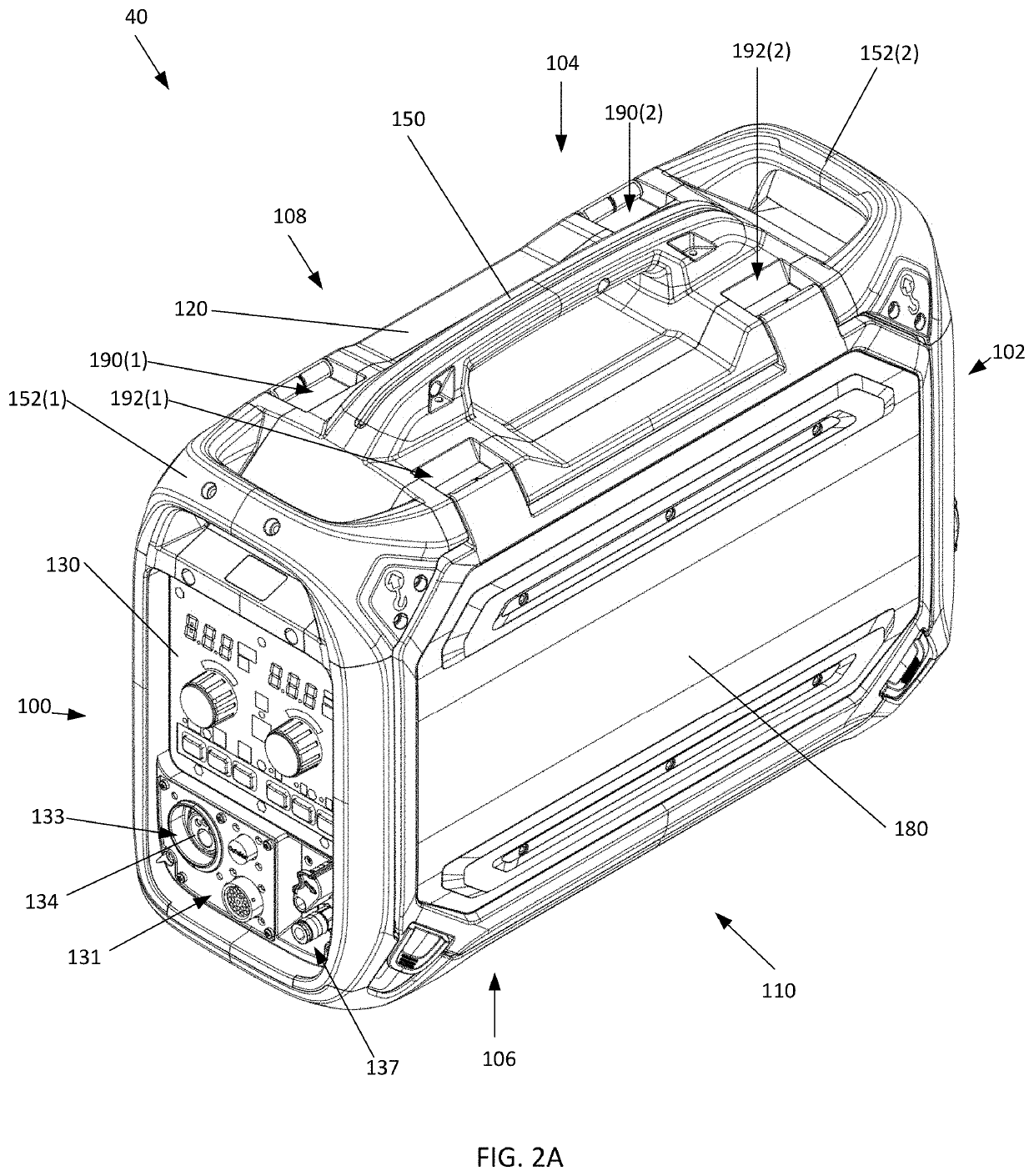
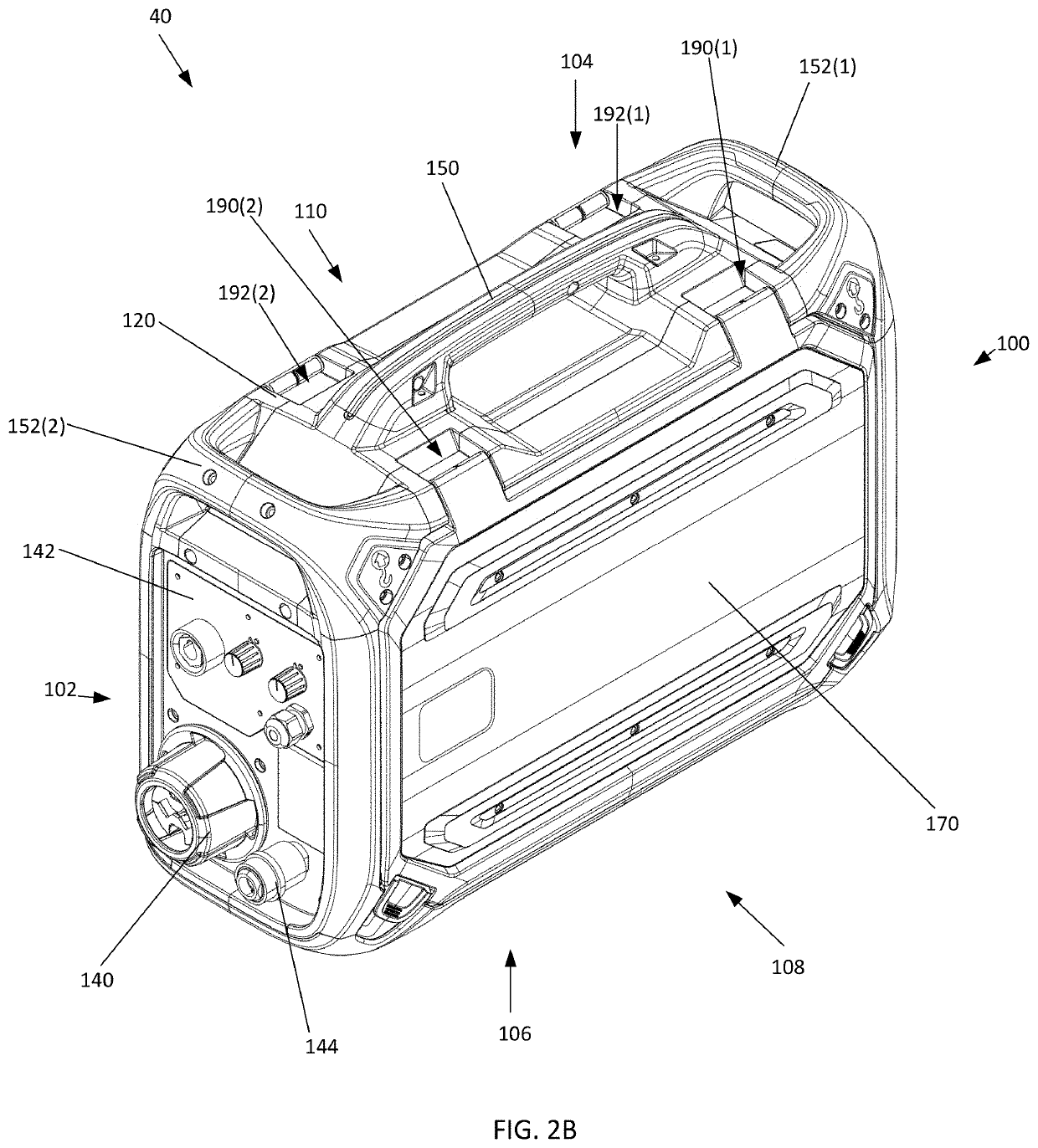
The present invention is a wire feeder for welding that has multiple features to improve its performance and make it more portable. The wire feeder has a double-walled housing with an interstitial space between the interior and exterior walls, which helps to reduce heat buildup and makes the wire feeder more robust and durable. The housing is flexible and resilient on the outside, while more rigid on the inside, which reduces its weight and makes it easier to transport. The interstitial space also allows for better cooling of the current bars and prevents polluted air from contaminating the components of the wire feeder. The access doors of the wire feeder have storage compartments for storing consumable components, and wear plates that can be easily replaced for different surfaces. The wire feeder can also be positioned horizontally on its side and wheeled into position for stability and ease of use.

Problems solved by technology

In addition, by having a closed-loop circulation path, polluted air from the exterior of the wire feeder is never pumped into the wire feeder, where the polluted air may contaminate the components disposed within the wire feeder.
This reduces the likelihood that the access doors become damaged (e.g., scratched, scuffed, dented, etc.), while the wear plates can be easily replaced when needed.

Method used


Image

  • Wire Feeder
  • Wire Feeder
  • Wire Feeder

Examples


Embodiment Construction

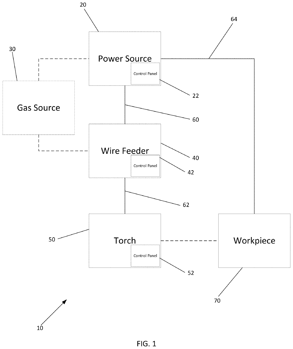
[0067]Turning to the drawings, FIG. 1 illustrates a schematic drawing of an embodiment of a welding system 10 which powers, controls, and provides supplies for a welding operation. The welding system 10 includes power source 20 having a control panel 22 through which a welding operator may control the welding output voltage, welding current, gas flow, and / or other welding parameters for the welding operation. The control panel 22 may include input or interface devices that the welding operator may use to adjust the welding parameters (e.g., voltage, current, etc.). The power source 20 may be connected to a gas source 30, which may be either external to the power source 20 (as shown in FIG. 1), or internal to the power source 20. The gas source 30 may provide the shielding gas for the welding operation.

[0068]As FIG. 1 illustrates, the welding system 10 also includes a wire feeder 40 that is connected to the power source 20 via at least one interconnection cable 60. The interconnectio...


PUM

PropertyMeasurementUnit
Lengthaaaaaaaaaa
Weightaaaaaaaaaa
Poweraaaaaaaaaa

Abstract

A wire feeder includes an exterior housing and in interior housing that creates an interstitial spaced that is disposed between the exterior and interior housing. This housing structure reduces weight of the wire feeder while maintaining the structural rigidness required of a wire feeder. This housing structure also promotes improved cooling features for the wire feeder and the components disposed within the wire feeder. The exterior housing may be constructed of a materials that reduces the likelihood of being damaged. The wire feeder may be further equipped with a strain relief device for the incoming supply cables, and an interchangeable cable connector. The wire feeder may also be equipped with removable wire guides for the wire feeder mechanism that are toolless. The wire feeder may be equipped with accessory storage and attachment features, as well as a cost reduced repositionable control panel.

Description

CROSS-REFERENCE TO RELATED APPLICATION[0001]This application is a continuation of International Application No. PCT / IB2019 / 059145, filed Oct. 24, 2019, which claims priority to provisional U.S. Application No. 62 / 754,853, filed Nov. 2, 2018, the entire contents of which are incorporated herein by reference.FIELD OF THE INVENTION[0002]The present invention relates to a wire feeder, and more specifically, a portable wire feeder for feeding welding wire and delivering power to a welding torch.BACKGROUND OF THE INVENTION[0003]Portable welding devices (e.g., a welding power supply, a wire feeder, etc.) are known, and are often embodied in a case. Such portable welding devices find use in applications where it is not practical or convenient to send a work-piece to a shop for repair or fabrication. Examples of applications for such portable welding devices include petroleum and chemical fabrication, shipboard installation and repair, and the like. Because of the portability of these weldin...

Claims


Application Information

Patent Timeline
IPC IPC(8): B23K9/10B23K37/00B23K9/12B23K9/32
CPCB23K9/1087B23K37/003B23K9/125B23K9/323B23K9/122B23K9/10B23K37/0282
Inventor DEKKER, JEROENGLÄDT, MATTIASLAGERKVIST, ARNESTJERNLÖF, FREDRIKFREDERIKSEN, NICLASJOHANSSON
Owner ESAB AB
Learn More