Vehicle air conditioner

a technology for air conditioners and vehicles, applied in vehicle heating/cooling devices, battery/fuel cell control arrangements, transportation and packaging, etc., can solve the problems of reducing air conditioning comfort in the occupant cabin, deterioration of batteries, and inability to warm the occupant cabin, so as to increase the air conditioning comfort in the vehicle cabin and restrict the deterioration of batteries

Active Publication Date: 2021-08-05
TOYOTA JIDOSHA KK
View PDF0 Cites 1 Cited by
  • Summary
  • Abstract
  • Description
  • Claims
  • Application Information

AI Technical Summary

Benefits of technology

[0005]In the above conventional heat pump system, it is not possible to warm the occupant cabin while cooling the battery. Therefore, there is room for improvement in increasing air conditioning comfort in the occupant cabin while restraining deterioration in the battery. For example, when the condition for permitting the cooling of the battery is the same regardless of the operation mode of the heat pump system, the battery can deteriorate and the air conditioning comfort in the occupant cabin can decrease.
[0006]The disclosure has been made for solving the above problem, and an object of the disclosure is to provide a vehicle air conditioner that makes it possible to increase the air conditioning comfort in the vehicle cabin while restraining the deterioration in the battery.
[0008]With this configuration, the switching to the battery cooling mode is permitted at an appropriate timing depending on the air cooling mode, and the switching to the battery cooling mode is permitted at an appropriate timing depending on the air heating mode. Thereby, it is possible to increase air conditioning comfort in a vehicle cabin while restraining deterioration in the battery.
[0017]In the above vehicle air conditioner that determines the switching from the air cooling mode to the battery cooling mode, the air cooling preference time may be set to a short time when a battery cooling request level that is decided depending on the temperature of the battery is high, and is set to a shorter time when the vehicle is traveling than when the vehicle is at a standstill.
[0020]With the vehicle air conditioner in the disclosure, it is possible to increase the air conditioning comfort in the vehicle cabin while restraining the deterioration in the battery.

Problems solved by technology

In the above conventional heat pump system, it is not possible to warm the occupant cabin while cooling the battery.
For example, when the condition for permitting the cooling of the battery is the same regardless of the operation mode of the heat pump system, the battery can deteriorate and the air conditioning comfort in the occupant cabin can decrease.

Method used


Image

  • Vehicle air conditioner
  • Vehicle air conditioner
  • Vehicle air conditioner

Examples


Embodiment Construction

[0035]Hereinafter, an embodiment of the disclosure will be described.

[0036]First, a configuration of a vehicle air conditioner 100 according to an embodiment of the disclosure will be described with reference to FIG. 1 and FIG. 2.

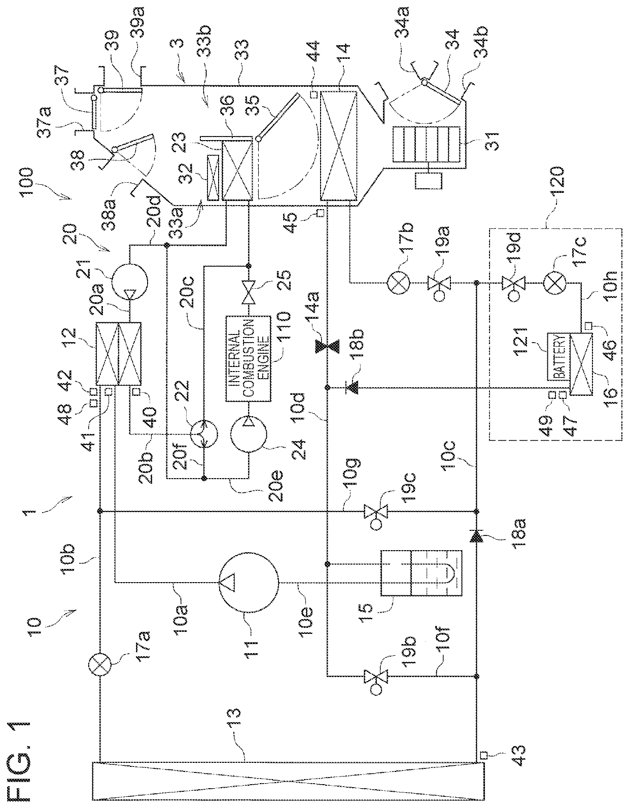
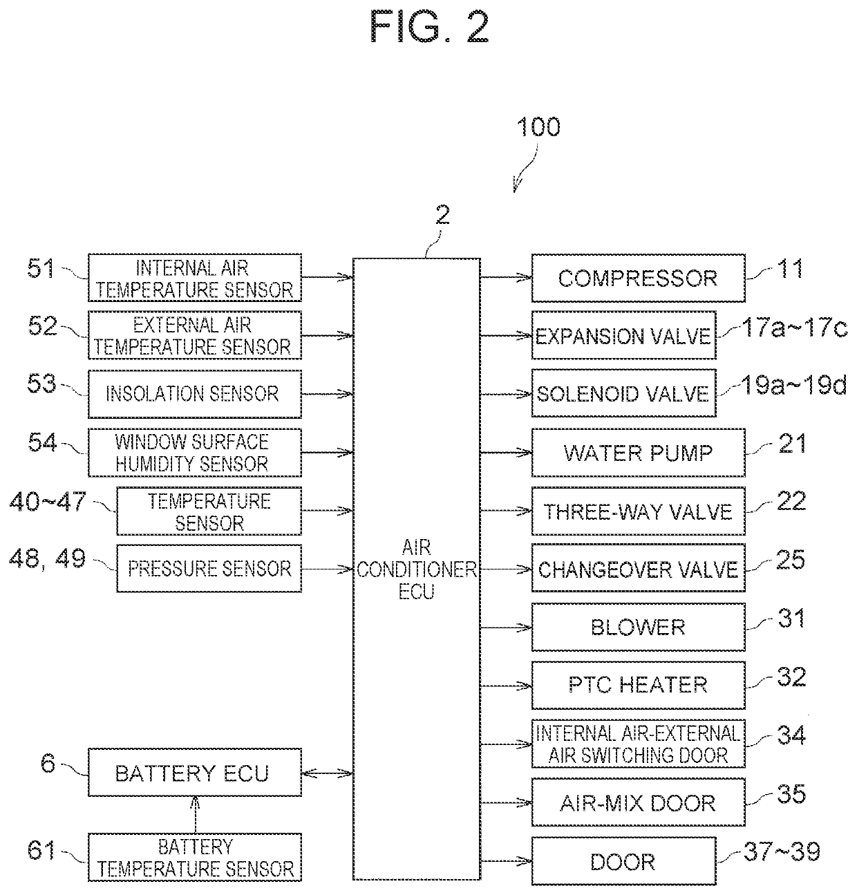
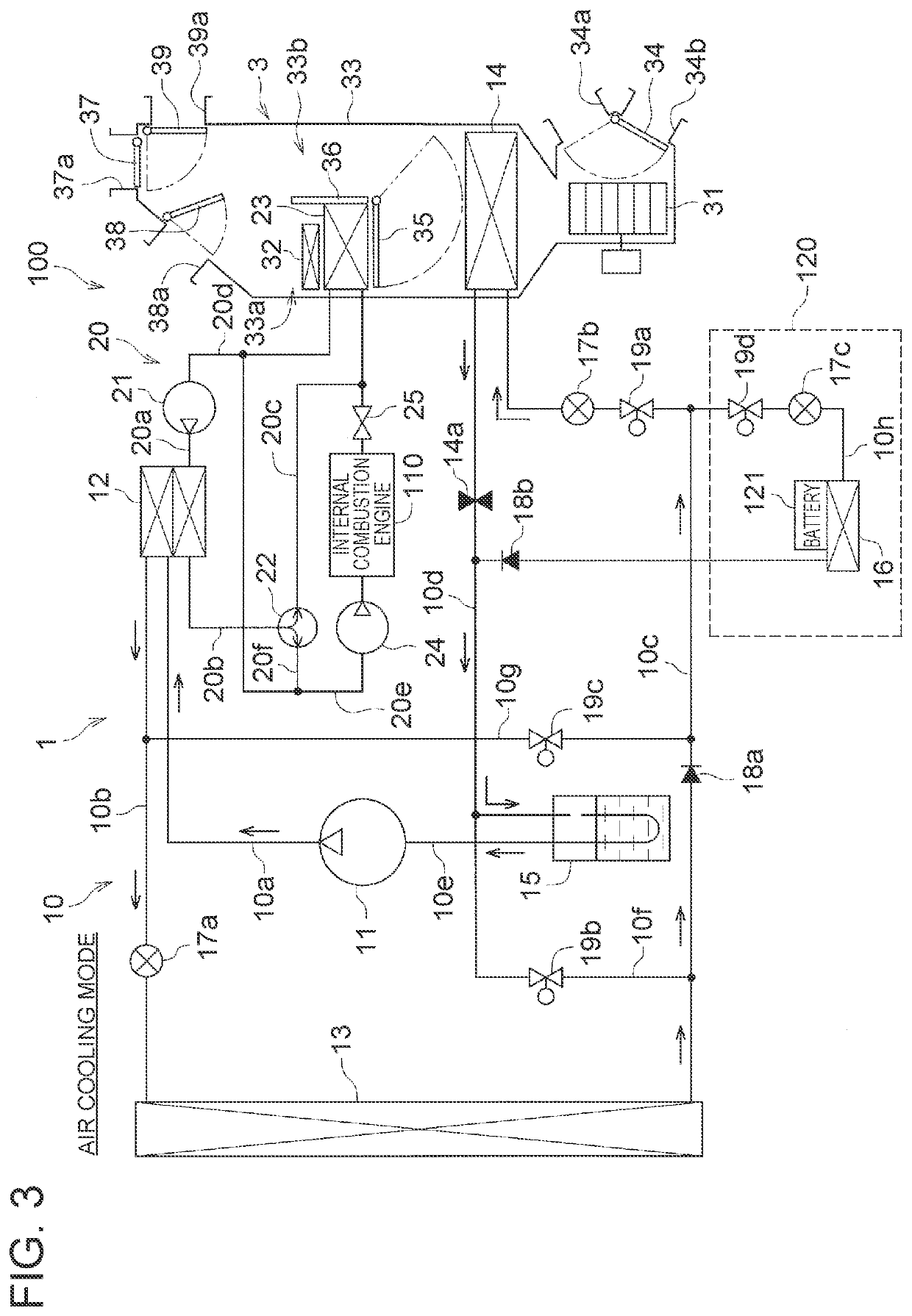
[0037]For example, the vehicle air conditioner 100 is applied to a plug-in hybrid vehicle that includes an internal combustion engine 110 and an electric motor (not illustrated) as a drive force source for vehicle travel. The plug-in hybrid vehicle is equipped with a battery pack 120, and the battery pack 120 contains a battery 121. The battery 121 is a high-tension battery that can be charged and discharged. The battery 121 is configured to supply electric power for driving the electric motor for vehicle travel, and to store electric power that is generated by the electric motor. As shown in FIG. 1, the vehicle air conditioner 100 includes a heat pump system 1, an air conditioner ECU 2 (see FIG. 2), and an inside air conditioning unit 3.

[0038]Heat Pump Sys...


PUM


Abstract

A vehicle air conditioner includes a heat pump system and an air conditioner ECU that controls the heat pump system. An operation mode of the heat pump system includes an air cooling mode, an air heating mode, a serial dehumidification air-heating mode, a parallel dehumidification air-heating mode, a battery-only cooling mode, and an air-cooling battery-cooling mode. The air conditioner ECU separately sets conditions for permitting cooling of a battery, depending on the operation mode.

Description

CROSS-REFERENCE TO RELATED APPLICATION[0001]This application claims priority to Japanese Patent Application No. 2020-013331 filed on Jan. 30, 2020, incorporated herein by reference in its entirety.BACKGROUND1. Technical Field[0002]The disclosure relates to a vehicle air conditioner.2. Description of Related Art[0003]Conventionally, a vehicle heat pump system that can switch between a cooling mode and a heating mode is known (see Japanese Unexamined Patent Application Publication No. 2017-171284 (JP 2017-171284 A), for example).[0004]The heat pump system in JP 2017-171284 A is configured to cool and heat an occupant cabin, and to cool a battery. The heat pump system includes an outside heat exchanger, an inside heat exchanger, a compressor, an intermediate heat exchanger and a battery cooler. In the cooling mode, a refrigerant that is circulated by the compressor is condensed in the outside heat exchanger, and is vaporized in the inside heat exchanger and the battery cooler. Then, us...

Claims


Application Information

Patent Timeline
Patent Type & Authority Applications(United States)
IPC IPC(8): B60H1/00B60H1/32
CPCB60H1/00278B60H1/3205B60H2001/3255B60H1/004B60H2001/3241B60H1/3227B60L58/26B60H1/3204B60H1/2225B60H3/024B60H1/00785B60H1/0075B60H1/00807B60H1/00814B60H2001/003B60H1/00921B60H2001/00928B60H2001/00949B60H2001/00307
Inventor SHIMAUCHI, TAKAYUKI
Owner TOYOTA JIDOSHA KK
Why Eureka
Try Eureka