Eureka AIR delivers breakthrough ideas for toughest innovation challenges, trusted by R&D personnel around the world.

Medium cassette and image recording apparatus

a cassette and image technology, applied in the field of medium cassette and image recording apparatus, can solve the problems of troublesome replacement operation of the roll sheet, large conveying resistance, and heavy weight of the entire roll

Pending Publication Date: 2021-08-05
BROTHER KOGYO KK
View PDF2 Cites 1 Cited by
  • Summary
  • Abstract
  • Description
  • Claims
  • Application Information

AI Technical Summary

Benefits of technology

The present patent aims to provide a medium cassette and an image recording apparatus that can conveniently replace a roll medium and detect if it is supported on a support part. Additionally, the apparatus is designed to identify if the recording medium is a roll medium or a single sheet medium, and correctly determine when the roll medium is used up.

Problems solved by technology

In a support configuration for the roll sheet in the feeder device, the replacement operation for the roll sheet may be troublesome.
That is, when consumption of the roll sheet is small and the residual amount is large, a weight of the entire roll is heavy, so that the conveying resistance is large.
However, it is not possible to detect the residual amount of the set roll sheet.
For this reason, it is necessary to newly provide a separate sensor so as to detect the residual amount of the roll sheet, which increases the manufacturing cost and enlarges the apparatus.
In the related-art recording apparatus, when the roll sheet whose rear end portion is not fixed to a winding core has run out, a part of the recording medium upstream of the nip position with respect to the conveying direction is in an unfixed state, so that it may be erroneously detected as a cut sheet.
As a result, it may not be possible to accurately detect that the sheet has run out.
Note that, the related-art does not disclose technology for determining which of the cut sheet and the roll sheet is set, in the configuration where the roll sheet is supported from below by the support part.
In this case, an image is erroneously recorded on the single sheet medium, so that the single sheet medium, a recording agent and time are wasted.

Method used


Image

  • Medium cassette and image recording apparatus
  • Medium cassette and image recording apparatus
  • Medium cassette and image recording apparatus

Examples


first embodiment

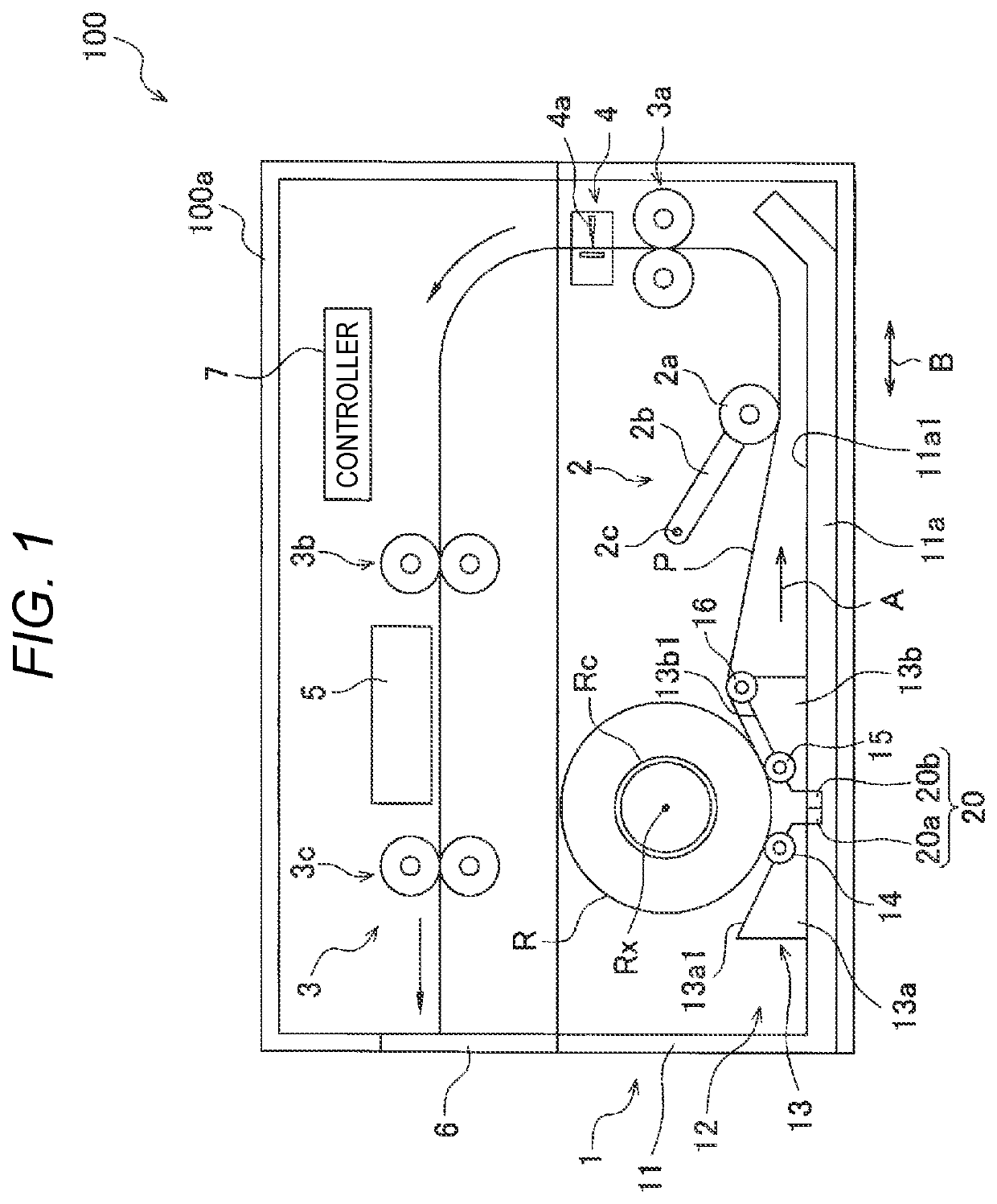
[0049]Hereinbelow, a printer 100 in which a sheet feeding cassette 1 in accordance with a first embodiment of the present disclosure is adopted will be described.

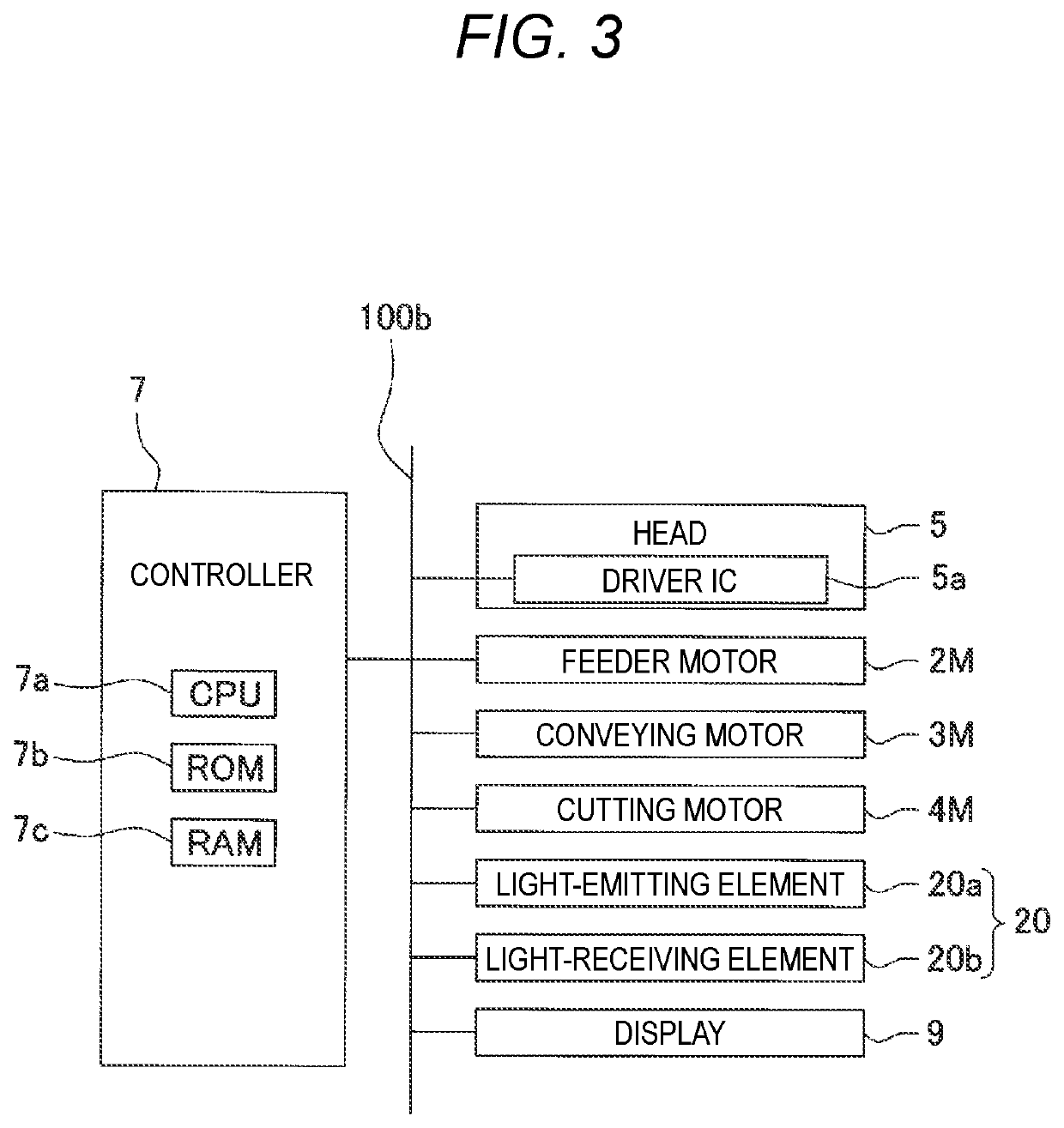
[0050]The printer 100 includes a housing 100a, a sheet feeding cassette 1, a sheet feeding unit 2, a conveying unit 3, a cutting unit 4, a head 5, a sheet discharge tray 6, and a controller 7. The sheet feeding cassette (medium cassette) 1 can be detachably mounted to a lower part of the housing 100a. The sheet discharge tray 6 configures one side wall of an upper part of the housing 100a, and can be opened and closed with respect to the housing 100a.

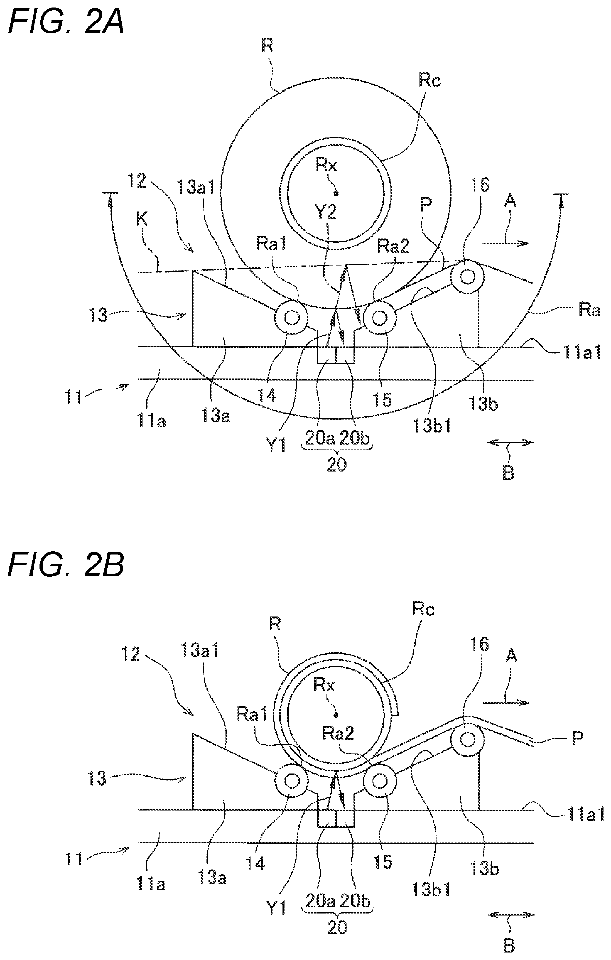
[0051]In the sheet feeding cassette 1, a roll sheet R corresponding to the “roll medium” of the present disclosure and a cut sheet K (shown with the dashed-dotted line in FIG. 2) corresponding to the “single sheet medium” of the present disclosure can be selectively accommodated. The roll sheet R has a configuration where a sheet P corresponding to the “continuous medium” of t...

second embodiment

[0088]

[0089]An overall configuration of an image recording apparatus 1001 in accordance with a second embodiment of the present disclosure is shown in FIG. 8. In FIG. 8, the image recording apparatus 1001 has an apparatus main body 1002. In the apparatus main body 1002, a supply unit 1003, a conveying unit 1004, an image forming unit 1005 and a discharge unit 1008 are provided. Note that, the image forming unit 1005 is an example of the recording unit. A side on which the discharge unit 1008 is provided is a front side of the image recording apparatus 1001, and a side on which the conveying unit 1004 is provided is a rear side of the image recording apparatus 1001. A side on which the supply unit 1003 is provided is a lower side of the image recording apparatus 1001, and a side on which the image forming unit 1005 is provided is an upper side of the image recording apparatus 1001.

[0090]

[0091]The supply unit 1003 includes a cassette 1030 detachably mounted to a lower part of the appa...

third embodiment

[0159]In the below, an inkjet printer (hereinbelow, simply referred to as “printer”) in accordance with a third embodiment of the present disclosure is described with reference to the drawings. In descriptions below, the upper and lower direction is defined based on a state (a state shown in FIG. 21) where a printer 2001 is equipped to be usable, the front and rear direction is defined based on a state where a side on which an opening 2013 of a housing 2011 is provided is a front side (front face), and the right and left direction is defined based on a state where the printer 2001 is seen from the front side (front face).

[0160]As shown in FIG. 21, the printer 2001 mainly includes a feeding cassette 2002, a feeding unit 2003, a conveying unit 2004, a cutting mechanism 2005, a recording unit 2006, a discharge tray 2007, a controller 2008, and the like. The feeding cassette 2002 is arranged below the recording unit 2006 in the housing 2011. The discharge tray 2007 is arranged in front ...


PUM

PropertyMeasurementUnit
Lengthaaaaaaaaaa
Forceaaaaaaaaaa
Angleaaaaaaaaaa

Abstract

A medium cassette of the present disclosure is a medium cassette configured to be inserted and removed with respect to an apparatus main body and capable of selectively accommodating any recording medium of a roll medium having a continuous medium which is wound in a roll shape and a single sheet medium.

Description

CROSS-REFERENCE TO RELATED APPLICATIONS[0001]This application is based upon and claims the benefit of priority from prior Japanese patent application No. 2020-017757 filed on Feb. 5, 2020, Japanese patent application No. 2020-058443 filed on Mar. 27, 2020, and Japanese patent application No. 2020-064155 filed on Mar. 31, 2020, the entire contents of which are incorporated herein by reference.TECHNICAL FIELD[0002]Aspects of the present disclosure relates to a medium cassette in which any recording medium of a roll medium and a single sheet medium can be selectively accommodated, and an image recording apparatus having the medium cassette.BACKGROUND ART[0003]Related-art discloses a feeder device configured to rotate a spool passing through a roll sheet in forward and reverse directions and to determine whether a recording medium is a cut sheet or a roll sheet based on a change in amount of bending of the recording medium.[0004]In addition, for example, related-art discloses an image r...

Claims


Application Information

Patent Timeline
IPC IPC(8): B41J15/04G03G15/00
CPCB41J15/044G03G15/6502B65H20/02B65H35/06B65H7/04B65H7/14B65H2701/1133B65H2701/1131B65H2801/03B65H2701/184B65H2701/182B65H2301/12G03G15/6517G03G15/6511
Inventor WATARI, TAKAHIKOHORI, YUJIYAMAGUCHI, MASATOMOMIMOTO, MASAOKODAMA, SHOKO
Owner BROTHER KOGYO KK
Why Eureka
Eureka Blog
Learn More