
A bead for a frame member

Active Publication Date: 2021-07-08
AANCO UK
View PDF0 Cites 0 Cited by
  • Summary
  • Abstract
  • Description
  • Claims
  • Application Information

AI Technical Summary

Benefits of technology

The invention is a bead that can be easily assembled and disassembled from a frame without damaging the frame or the bead. The bead is made from materials such as timber, PVC, or aluminium, and has a resiliently deformable member made of plastic or other polymer materials. This bead allows for quick and easy attachment and release from the frame, reducing installation and replacement time while also reducing the risk of damaging the bead or frame.

Problems solved by technology

One of the drawbacks with existing glazing beads is the time taken to install a door or window.
The process of fitting the glazing bead properly such that the gaskets apply an appropriate force to secure the glazing in place requires considerable skill and time to perform.
If this process is rushed and the glazing unit or the gasket is damaged during installation, an installer will need to replace the damaged piece and start again from the beginning.
Furthermore, the door or window may not allow for disassembly, as the joints used to secure the frame in place may not be releasable.
In this case, an installation may be further delayed.
This approach is only viable because of the flexibility of PVC.
If the glazing is within an aluminium frame system, using the previously described method carries a high risk of causing considerable aesthetic damage, as well as structural damage to the frame and the glazing bead.
Typically, this results in damage to the gasket and therefore a replacement wedge gasket is often required when replacing a glazing unit.
This is both time-inefficient and cost-inefficient.

Method used


Image

  • A bead for a frame member
  • A bead for a frame member
  • A bead for a frame member

Examples


Embodiment Construction

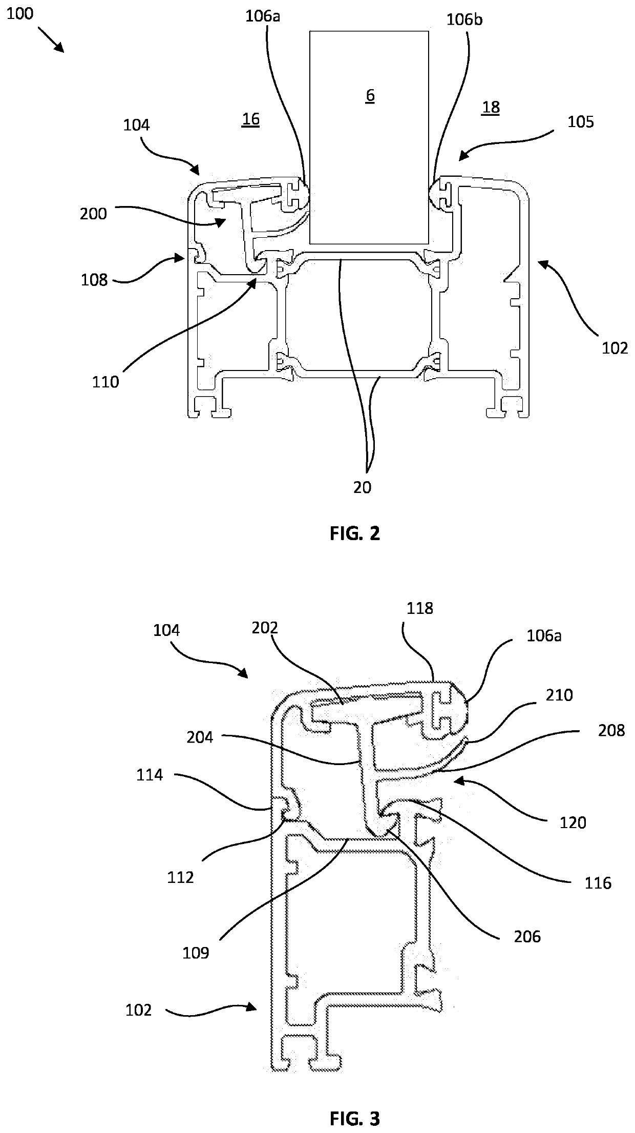
[0032]While the subsequent description is in relation to windows or doors having a glazing bead to secure a glazing unit, typically a sheet of glass, the application of the present invention is not limited to windows and doors, but to any such system having a glazing unit secured by a glazing bead.

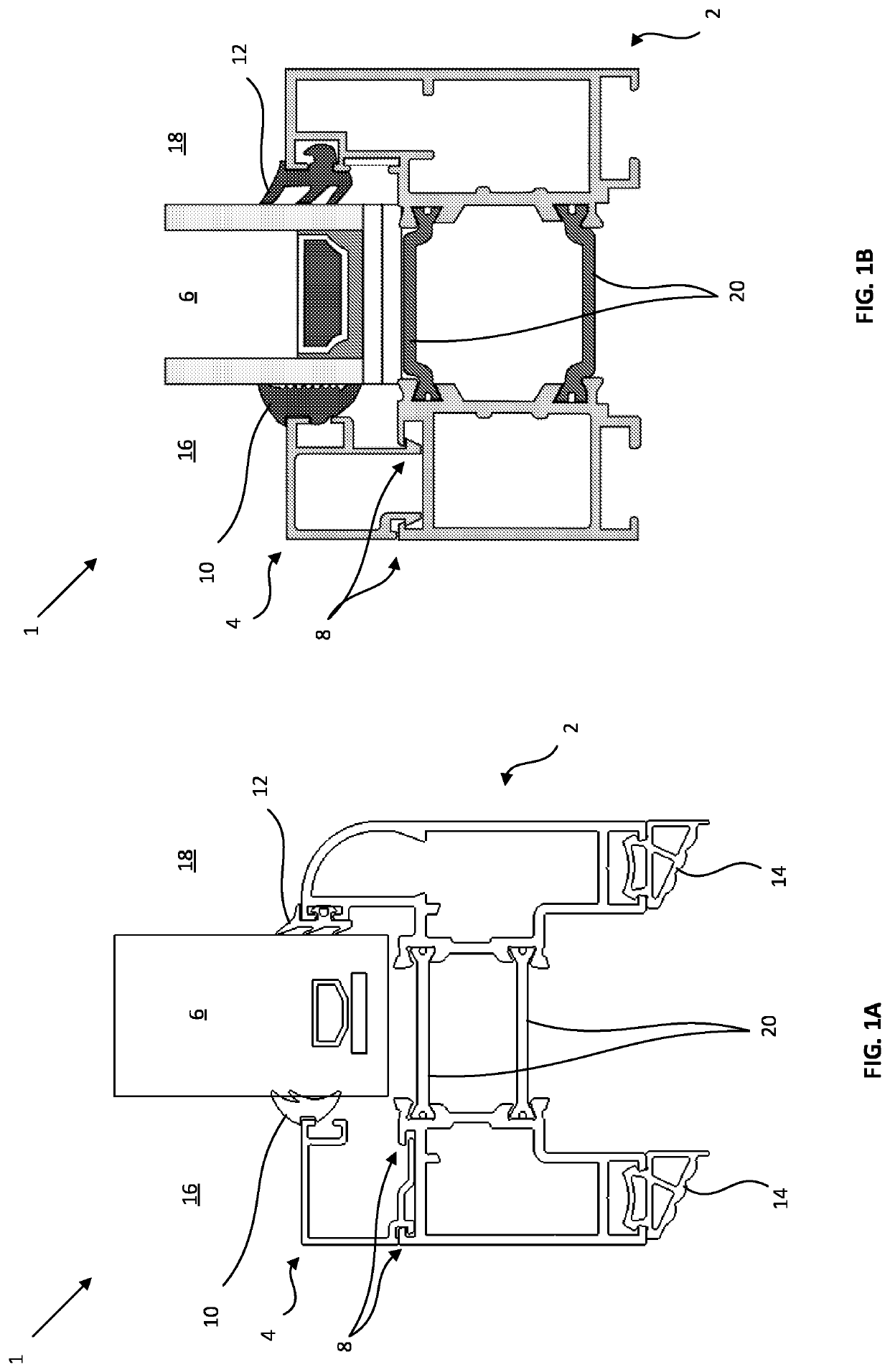
[0033]FIGS. 1A & 1B illustrate prior art frame systems. FIGS. 1A and 1B each illustrate a frame system 1 having a frame 2 and a bead 4 which act to compress glazing 6 between a wedge gasket 10 and a flipper gasket 12. The bead 4 is shown secured to the frame 2 on the inside 16 of a space by two mechanical snap-fit joints. The frame system 1 is also shown incorporating a thermal break 20 to improve the thermal efficiency of the frame system 1. The thermal break spaces the two halves of the frame member 2 and traps a pocket of air within the frame 2 to reduce the thermal conductivity of the frame 2. Outer frame gaskets 14 are also shown secured to the frame 2 of FIG. 1A to provide a watertig...


PUM


Abstract

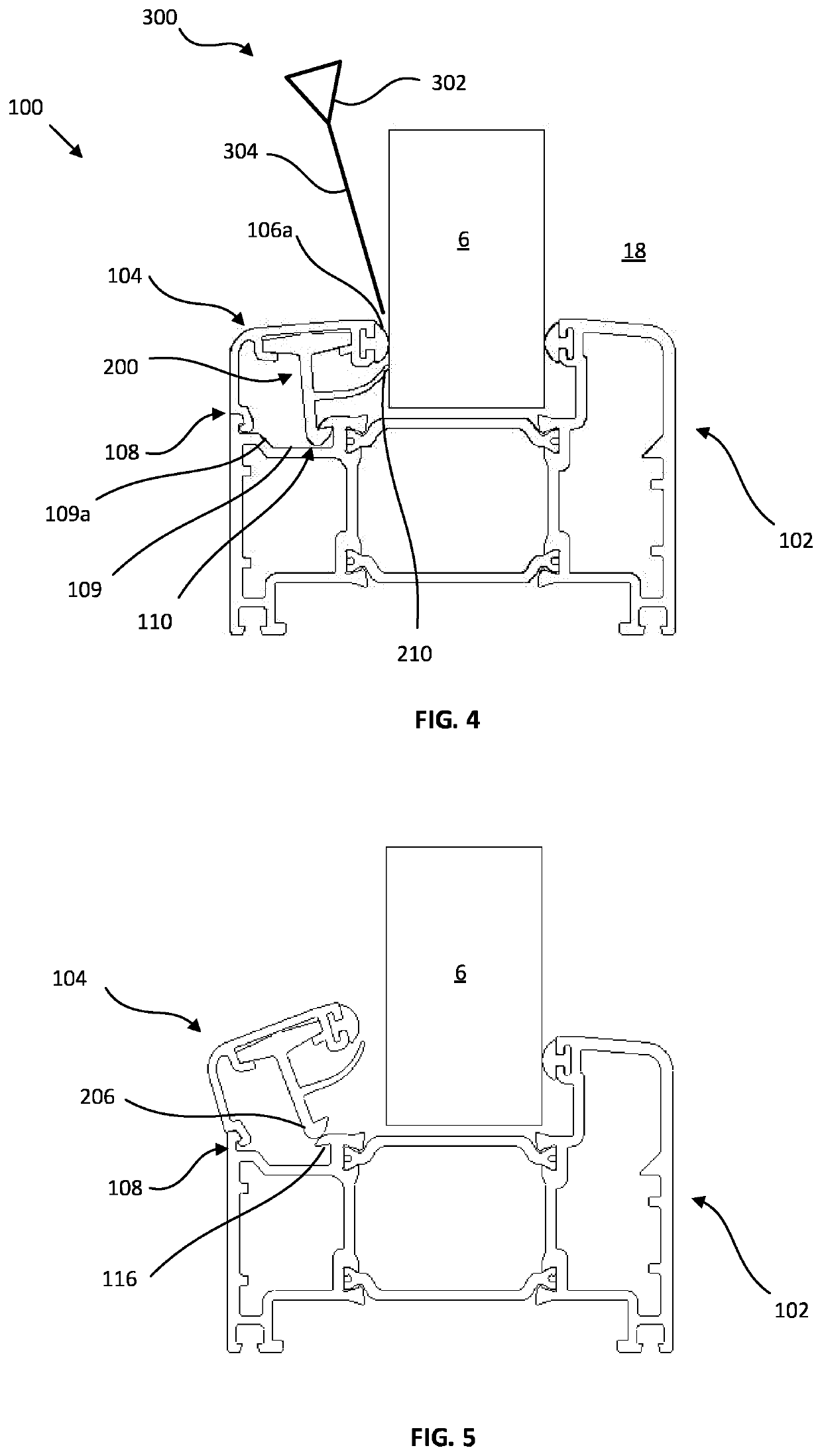
A bead for releasably securing a glazing unit to a frame member, comprising a body having a first end and a second end, and a resiliently deformable member secured to the body and having a first finger extending from the body to a first end, and a second finger extending from the first finger to a second end. The first end of the body and the first end of the first finger are configured to engage with respective first and second ends of a frame member so as to secure the bead to the frame member. The second end of the body is configured to releasably secure a gasket in a first position so as to secure a glazing unit against an opposed end of the frame member. In use, application of an external force to the gasket moves the gasket to a second position and deflects the second finger from a first position to a second position, and the first finger is configured to separate from the second end of the frame member upon deflection of the second finger to the second position, so as to release the bead from the frame member.

Description

[0001]This invention relates to a bead for releasably securing a glazing unit to a frame member.BACKGROUND[0002]Doors or windows incorporating glazing typically utilise a glazing bead to sandwich the glazing unit, often a sheet of glass, in the door or window frame. The bead is typically used in combination with a gasket, as this allows the bead to apply a force against the glass without damaging the glass when the bead is secured in place. The bead sandwiches the glazing between opposed gaskets which and applies a compressive force to hold the glazing securely in place. The gaskets also create a watertight seal around the perimeter of the glazing, which prevents liquid from passing around the glazing in the frame of the door or window and passing through the door or window. Without the bead, the glazing unit would not be held securely in the door or window frame.[0003]One of the drawbacks with existing glazing beads is the time taken to install a door or window. The process of fitt...

Claims


Application Information

Patent Timeline
IPC IPC(8): E06B3/58E06B3/54
CPCE06B3/5828E06B3/26301E06B3/5409E06B3/5821E06B3/549E06B3/5481
Inventor FIELDING, THOMAS ANDREW
Owner AANCO UK
Learn More