Radar apparatus and signal processing method
a signal processing and radar technology, applied in the field of radar techniques, can solve the problems of energy loss (integration loss) during coherent integration, the pulse repetition interval is not constant, and the phase change of the received signal, etc., to achieve the effect of improving target detection performance and suppressing integration loss
- Summary
- Abstract
- Description
- Claims
- Application Information
AI Technical Summary
Benefits of technology
Problems solved by technology
Method used
Image
Examples
first embodiment
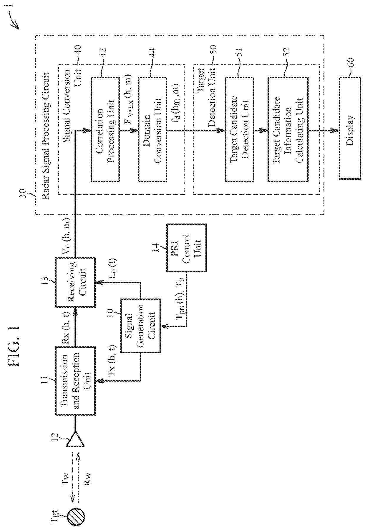
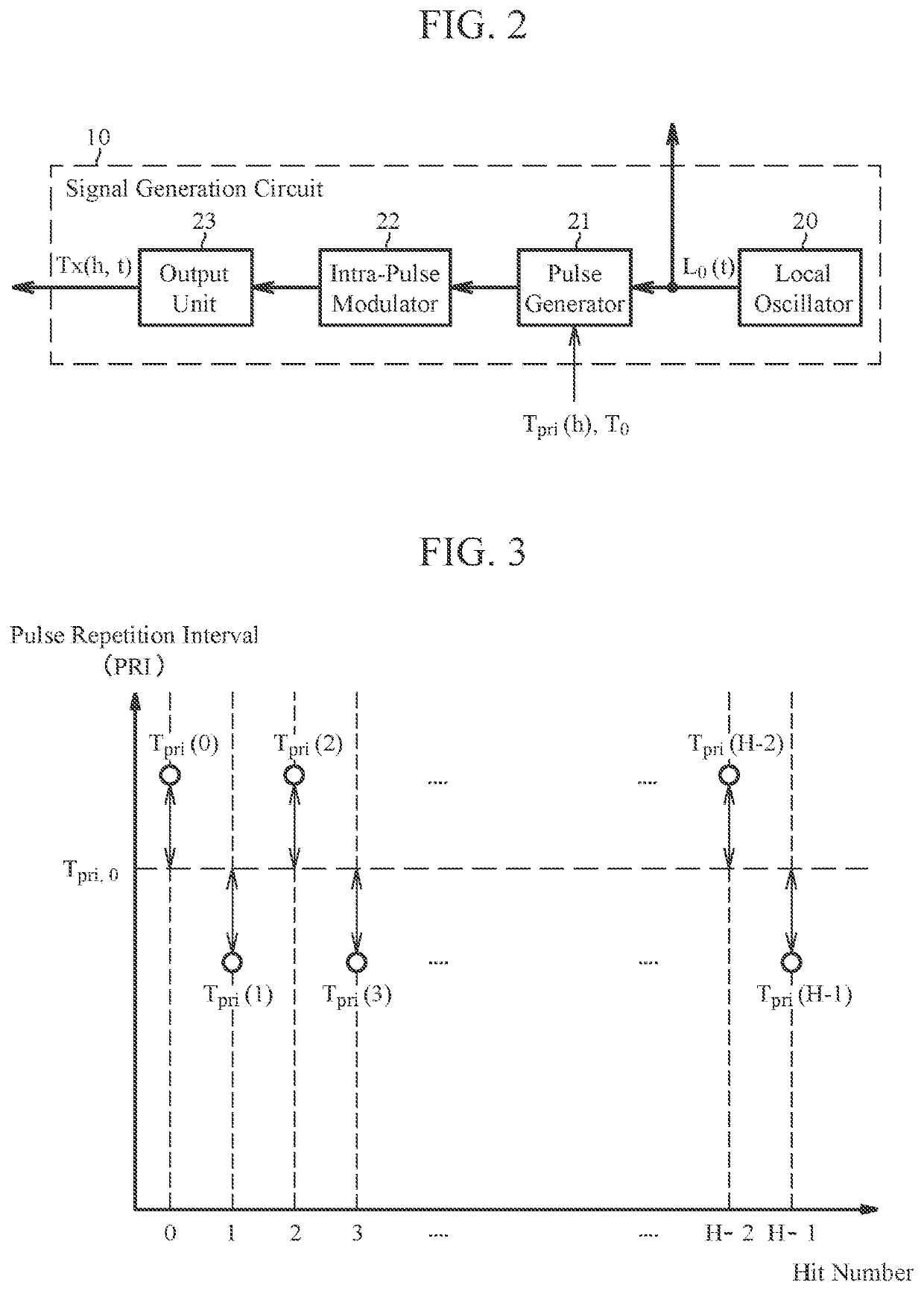
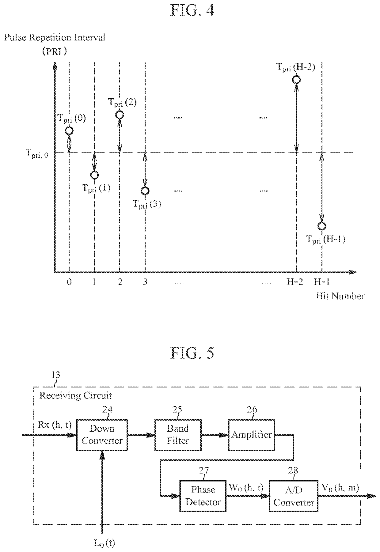
[0028]FIG. 1 is a block diagram showing a schematic configuration of a radar apparatus 1 according to a first embodiment of the present invention. As shown in FIG. 1, the radar apparatus 1 includes: a signal generation circuit 10 that generates a plurality of transmission pulse signals Tx(h,t) at a timing based on pulse repetition intervals (PRIs) Tpri(h); a transmission and reception unit 11 that outputs the plurality of transmission pulse signals Tx(h,t) to an antenna (aerial) 12 and then receives a plurality of reflected wave signals Rx(h,t) corresponding to the respective plurality of transmission pulse signals Tx(h,t); a receiving circuit 13 that performs analog signal processing on the plurality of reflected wave signals Rx(h,t) to generate a plurality of received analog signals W0(h,t) and converts the respective plurality of analog signals W0(h,t) into a plurality of received digital signals (received video signals) V0(h,m); a radar signal processing circuit 30 that performs...
second embodiment
[0090]FIG. 10 is a block diagram schematically showing a configuration of a radar apparatus 2 according to a second embodiment of the present invention. As shown in FIG. 10, the radar apparatus 2 includes a signal generation circuit 10, a transmission and reception unit 11, a receiving circuit 13, a radar signal processing circuit 31, and a display 60. The configuration of the radar apparatus 2 in the present embodiment is the same as the configuration of the radar apparatus 1 in the first embodiment, except that the radar signal processing circuit 31 in FIG. 10 is provided instead of the radar signal processing circuit 30 in the first embodiment, and the PRI control unit 15 in FIG. 10 is provided instead of the PRI control unit 14 in the first embodiment.
[0091]The PRI control unit 15 in the present embodiment has a PRI setting unit 15a and a GCD setting unit 15b. Similarly to the PRI control unit 14 in the first embodiment, the PRI setting unit 15a supplies a pulse width To and a s...
third embodiment
[0124]FIG. 15 is a block diagram schematically showing a configuration of a radar apparatus 3 according to a third embodiment of the present invention. The configuration of the radar apparatus 3 in the present embodiment is the same as the configuration of the radar apparatus 2 in the second embodiment, except that a PRI control unit 16 in FIG. 15 is provided in place of the PRI control unit 15 in the second embodiment.
[0125]The PRI control unit 16 in the present embodiment includes a PRI setting unit 16a and a GCD setting unit 16b. The PRI setting unit 16a supplies a pulse width T0 and a series of unequally spaced pulse repetition intervals Tpri(0) to Tpri(H−1) to a signal generation circuit 10. The series of pulse repetition intervals Tpri(0) to Tpri(H−1) is not limited to a pair of a pulse repetition interval longer than a reference interval Tpri,0 and a pulse repetition interval shorter than the reference interval Tpri,0. For example, the PRI setting unit 16a can set a random or...
PUM
 Abstract
Description
Claims
Application Information
 - R&D Engineer
- R&D Manager
- IP Professional
- Industry Leading Data Capabilities
- Powerful AI technology
- Patent DNA Extraction
Browse by: Latest US Patents, China's latest patents, Technical Efficacy Thesaurus, Application Domain, Technology Topic, Popular Technical Reports.
© 2024 PatSnap. All rights reserved.Legal|Privacy policy|Modern Slavery Act Transparency Statement|Sitemap|About US| Contact US: help@patsnap.com


