Trimmer Head with Residual Trimmer Line Indicator

a technology of residual trimmer and indicator, which is applied in the direction of mowers, agricultural tools and machines, mowers, etc., can solve the problems of recognizing the residual trimmer line length, and using the trimmer line which is subject to a certain wear and tear

Pending Publication Date: 2021-06-24
ANDREAS STIHL AG & CO KG
View PDF1 Cites 2 Cited by
  • Summary
  • Abstract
  • Description
  • Claims
  • Application Information

AI Technical Summary

Benefits of technology

The patent is about a trimmer head for a garden tool. The trimmer head has a spool that holds a trimmer line and an actuating element that helps determine how long the line is. This is important because the actuating element allows for precise measurement of the rotation angle between the spool and the housing, which is important for ensuring the proper function of the trimmer head. The trimmer line is pushed through a channel in the spool and then wound onto the spool. The spool also has holding devices that enable the use of two trimmer lines simultaneously. These technical features make the trimmer head more efficient and reliable.

Problems solved by technology

As a tool, trimmer lines are used which are subject to a certain wear in operation of the trimmer head.
A disadvantage of such systems is that the recognition of the residual trimmer line length is possible only as a function of the trimmer line type.

Method used


Image

  • Trimmer Head with Residual Trimmer Line Indicator
  • Trimmer Head with Residual Trimmer Line Indicator
  • Trimmer Head with Residual Trimmer Line Indicator

Examples


Embodiment Construction

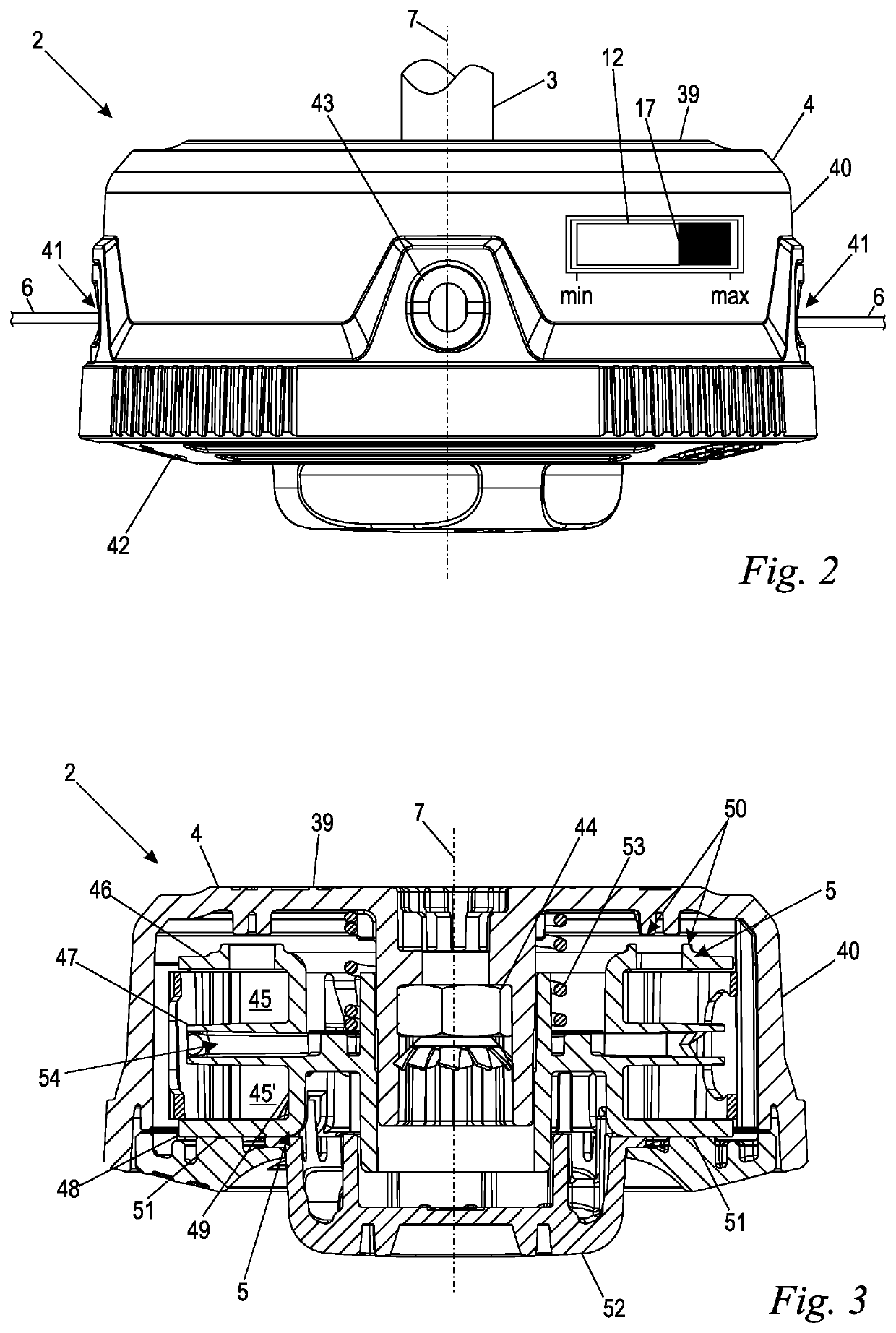
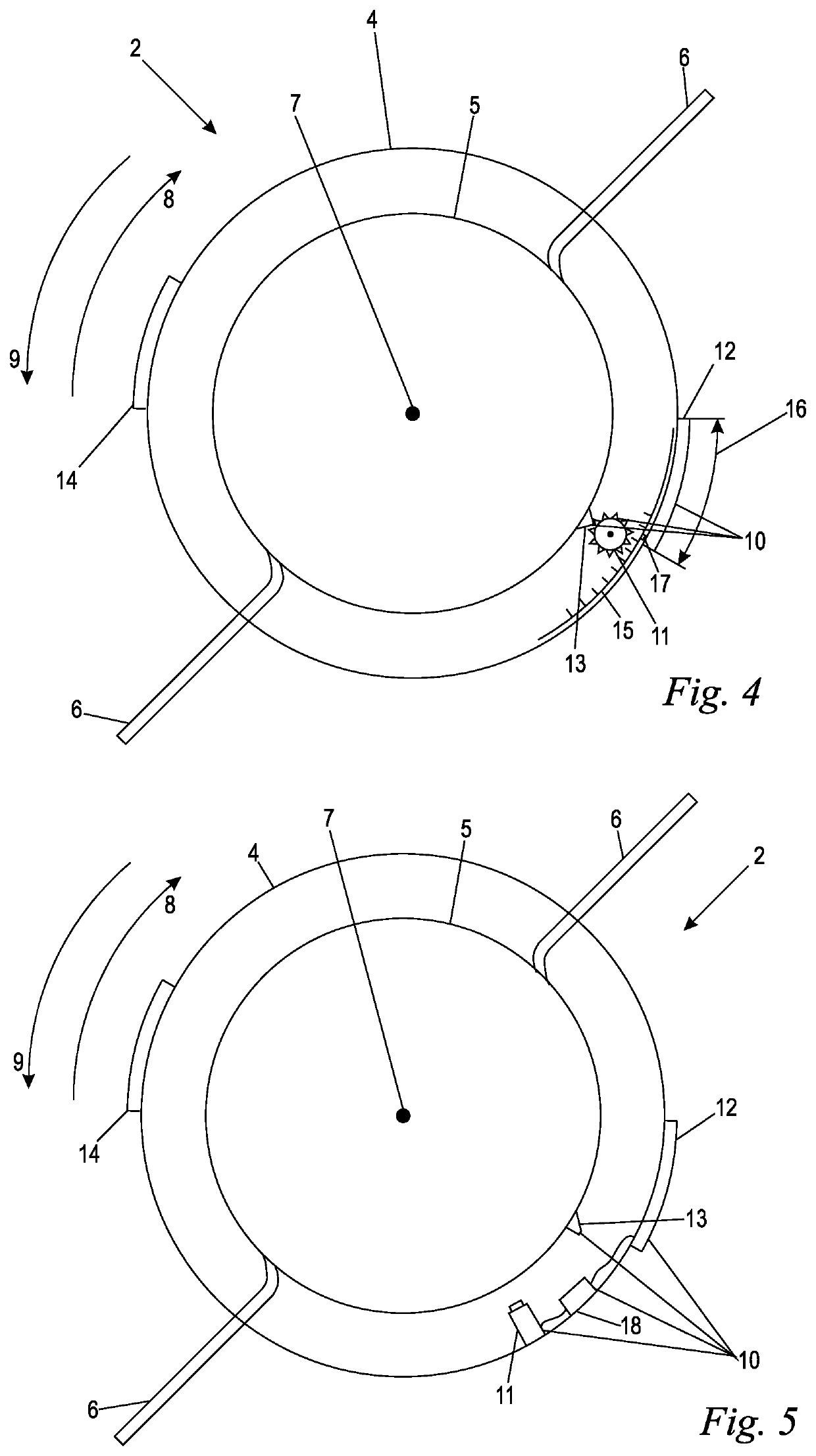
[0022]FIG. 1 shows a trimmer 1 in a schematic illustration. The trimmer 1 is held by an operator 30. The trimmer 1 comprises a rearward end with a rearward housing 31 and a front end from which a drive shaft 3 (FIG. 2) projects. A shaft 32 connects the rearward end and the front end. Handles 55 for guiding the trimmer 1 are arranged at the shaft 32. A trimmer head 2 adjoins the front end of the trimmer 1. The trimmer head 2 is fastened to the drive shaft 3 and is driven in rotation about an axis of rotation 7 by a drive motor 33, only schematically indicated, in a rotational direction 34 for work. The drive motor 33 is arranged in the rearward housing 31 wherein a drive shaft is extending in the shaft 32. It can be provided that this drive shaft is connected inside the shaft immediately to the drive shaft 3 for the trimmer head 2 so that no gearbox is positioned inbetween. In an alternative embodiment, not illustrated, the drive motor 33, which is in particular an electric motor, ca...


PUM


Abstract

A trimmer head for mounting on a drive shaft of a trimmer has a housing and a trimmer line spool for winding and unwinding a trimmer line. The trimmer line spool is rotatably supported in the housing about an axis of rotation. The trimmer line spool has a first rotational direction in relation to the housing and a second rotational direction in relation to the housing, wherein the second rotational direction is opposite to the first rotational direction. A counting device detects a residual trimmer line length of the trimmer line remaining on the trimmer line spool. The counting device is connected to the trimmer line spool such that the counting device counts up when the trimmer line spool rotates in relation to the housing in the first rotational direction and counts down when the trimmer line spool rotates in relation to the housing in the second rotational direction.

Description

BACKGROUND OF THE INVENTION[0001]The invention relates to a trimmer head for mounting on a drive shaft of a trimmer.[0002]A trimmer serves for mowing grass, shrub or the like. For this purpose, a trimmer head with a tool is driven in rotation about an axis of rotation of the trimmer head so that the grass is cut off upon contact with the tool. As a tool, trimmer lines are used which are subject to a certain wear in operation of the trimmer head. During operation of a trimmer head, the trimmer line must be readjusted several times so that a sufficient length of trimmer line is available and the cutting function of the trimmer head is not impaired. When the trimmer line is completely unwound from the trimmer line spool, a new trimmer line must be inserted into the trimmer head.[0003]It is advantageous when the operator is enabled to anticipate an upcoming change of the trimmer line. This enables the operator to keep at hand a replacement trimmer line and to change at the site of use t...

Claims


Application Information

Patent Timeline
IPC IPC(8): A01D34/416
CPCA01D34/4163A01D34/416A01D34/001
Inventor HOCHE, FLORIAN
Owner ANDREAS STIHL AG & CO KG
Why Eureka
Try Eureka