
Nuclear reactor decommissioning system

a nuclear reactor and decommissioning technology, applied in the field of nuclear reactor decommissioning system, can solve the problems of radioactive dust such as aerosol and slag diffusion and contamination of peripheral devices, and achieve the effect of minimizing radioactive dust and easy adjustment of shielding device length

Active Publication Date: 2021-06-17
KOREA HYDRO & NUCLEAR POWER CO LTD
View PDF0 Cites 0 Cited by
  • Summary
  • Abstract
  • Description
  • Claims
  • Application Information

AI Technical Summary

Benefits of technology

The invention is a shielding device that can be adjusted in length to block the diffusion of radioactive dust generated during a cutting process. The device is installed between a reactor and a lifting device, and it has a ventilation part that helps to collect the radioactive dust and minimize its contamination and exposure to workers. The technical effect of the invention is to provide a reliable and efficient barrier to protect against the risk of radiation contamination during cutting operations.

Problems solved by technology

Since the reactor of such a pressurized water reactor type of nuclear power plant is contaminated with radioactivity, when the reactor is cut and dismantled, radioactive dust such as aerosol and slag may diffuse and contaminate peripheral devices.

Method used


Image

  • Nuclear reactor decommissioning system
  • Nuclear reactor decommissioning system
  • Nuclear reactor decommissioning system

Examples


Embodiment Construction

[0020]The present invention will be described more fully hereinafter with reference to the accompanying drawings, in which embodiments of the invention are shown. As those skilled in the art would realize, the described embodiment may be modified in various different ways, all without departing from the spirit or scope of the present invention.

[0021]In order to clearly describe the present invention, parts that are irrelevant to the description are omitted, and identical or similar constituent elements throughout the specification are denoted by the same reference numerals.

[0022]Further, in the drawings, the size and thickness of each element are arbitrarily illustrated for ease of description, and the present disclosure is not necessarily limited to those illustrated in the drawings.

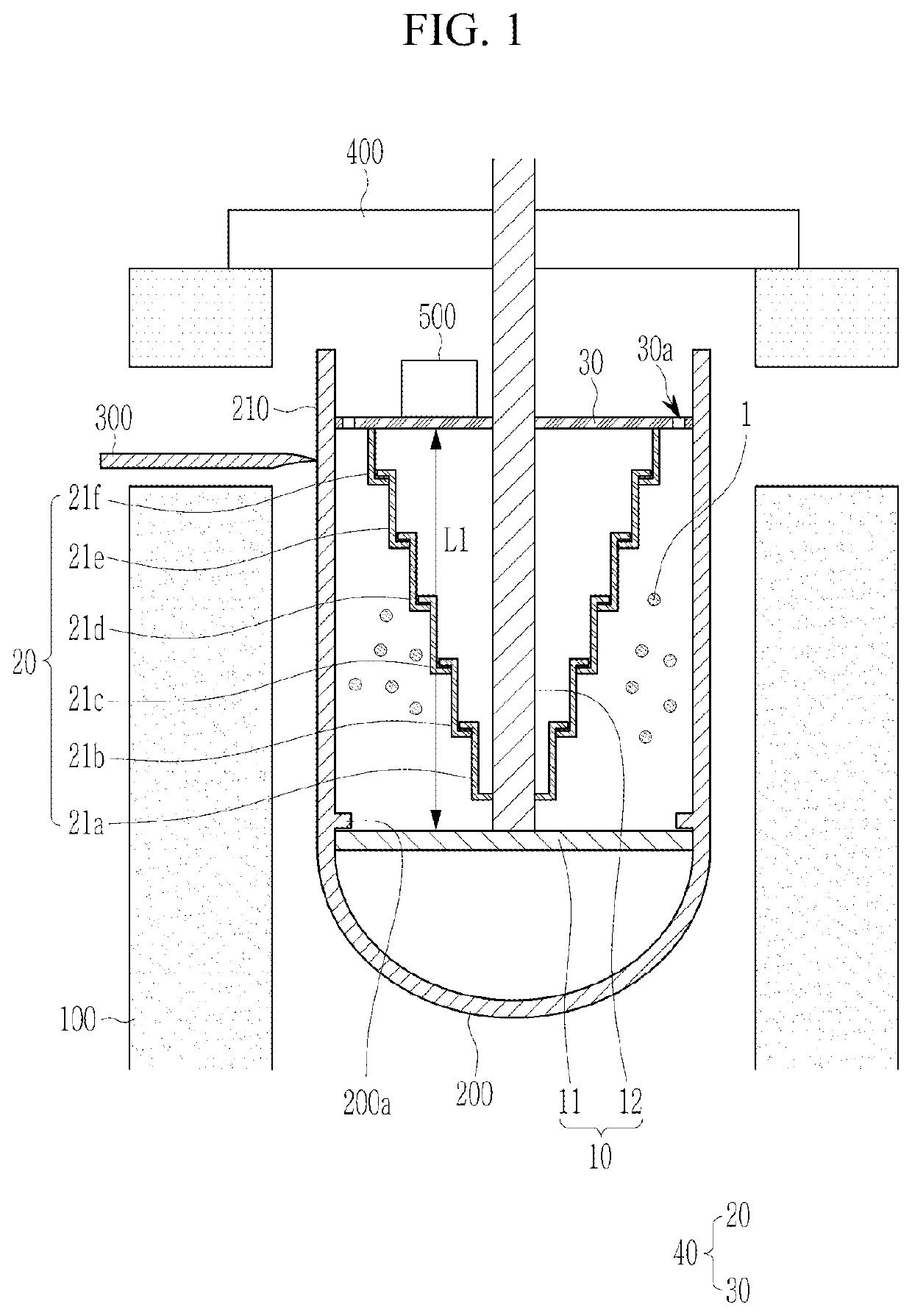
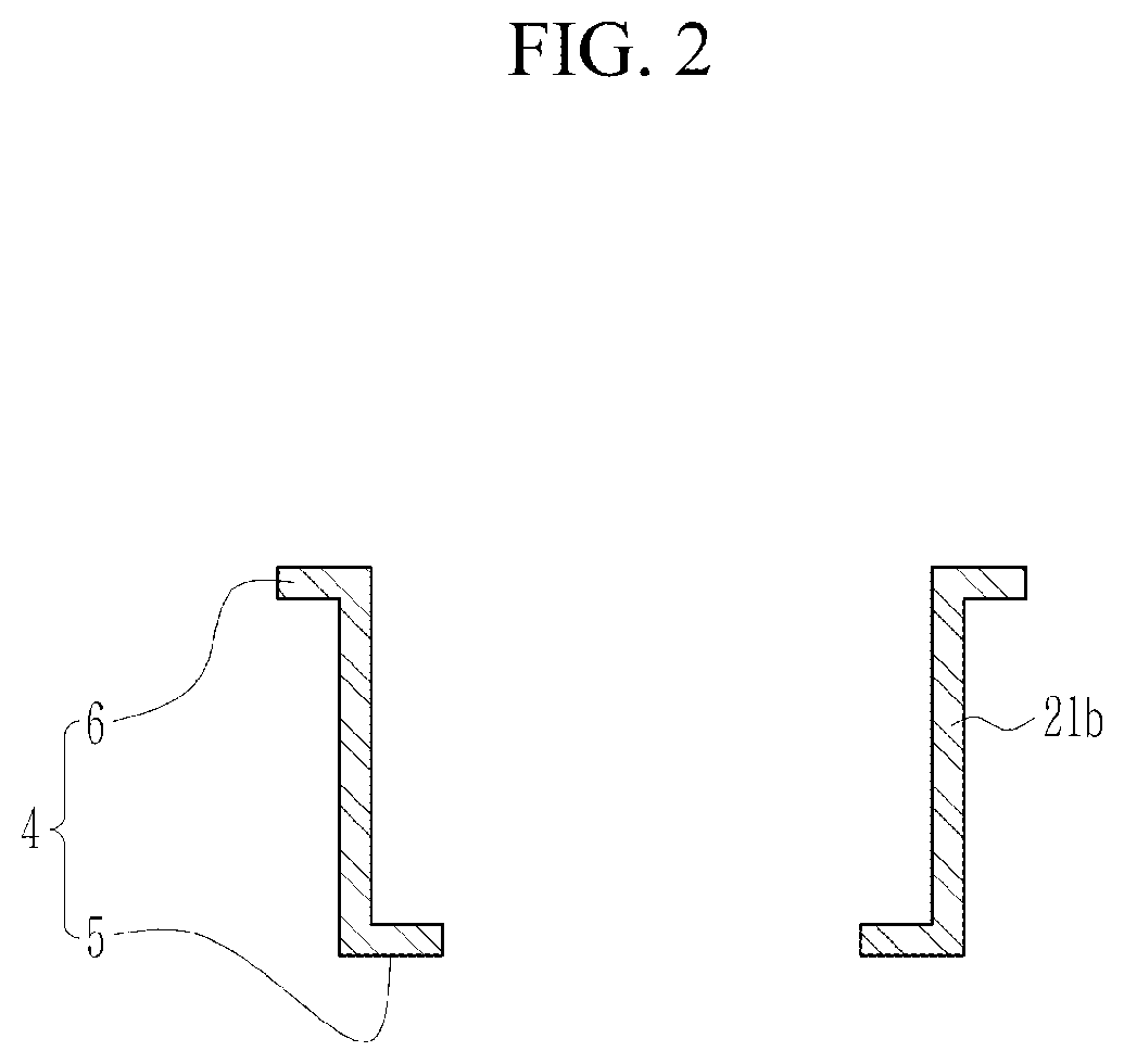
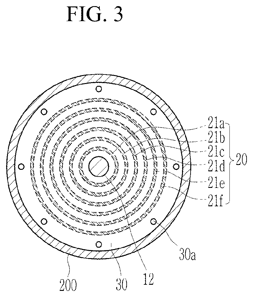
[0023]FIG. 1 illustrates a cross-sectional view of a nuclear reactor decommissioning system according to an embodiment, FIG. 2 illustrates an enlarged cross-sectional view of one cylindrical member of F...


PUM


Abstract

A nuclear reactor decommissioning system according to an embodiment includes a cutting device to cut a reactor, a lifting device inserted inside the reactor to lift the reactor, and a shielding device that is positioned between the reactor and the lifting device and blocks radioactive dust generated by the cutting device from spreading.

Description

TECHNICAL FIELD[0001]The present invention relates to a nuclear reactor decommissioning system.BACKGROUND ART[0002]As fossil energy is depleted worldwide, nuclear power generation is being used as a major energy source. In such nuclear power generation, a generally-used pressurized water reactor (PWR) nuclear power plant consists of a primary system circulating through a nuclear reactor, a secondary system circulating through a steam generator, and a tertiary system circulating through a condenser. Specifically, in the primary system, pressure is applied to a coolant in a reactor to maintain a pressure of 150 atm and 300° C., and in the secondary system, the coolant passes through tubes of a steam generator and boils water of the steam generator side to generate steam to turn a turbine. In the tertiary system, the steam turns the turbine, and then passes through the condenser and becomes water again and is sent to the steam generator.[0003]Since the reactor of such a pressurized wat...

Claims


Application Information

Patent Timeline
IPC IPC(8): G21D1/00
CPCG21D1/003Y02E30/30Y02E30/00G21F7/06G21F9/28G21C1/086
Inventor HWANG, YOUNG HWANLEE, MI-HYUNYOON, JU-YOUNGKIM, CHEON-WOO
Owner KOREA HYDRO & NUCLEAR POWER CO LTD
Learn More