
Thin backlight module and manufacturing method thereof

Active Publication Date: 2021-06-17
WUHAN CHINA STAR OPTOELECTRONICS TECH CO LTD
View PDF0 Cites 2 Cited by
  • Summary
  • Abstract
  • Description
  • Claims
  • Application Information

AI Technical Summary

Benefits of technology

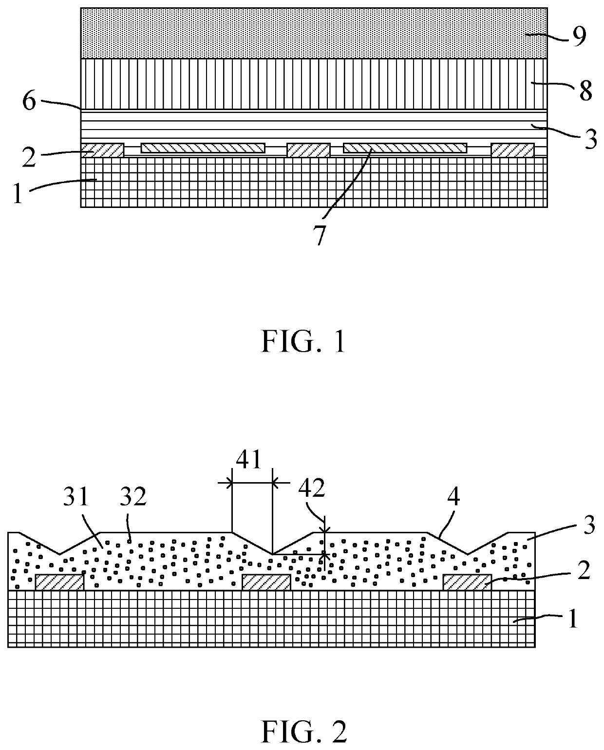
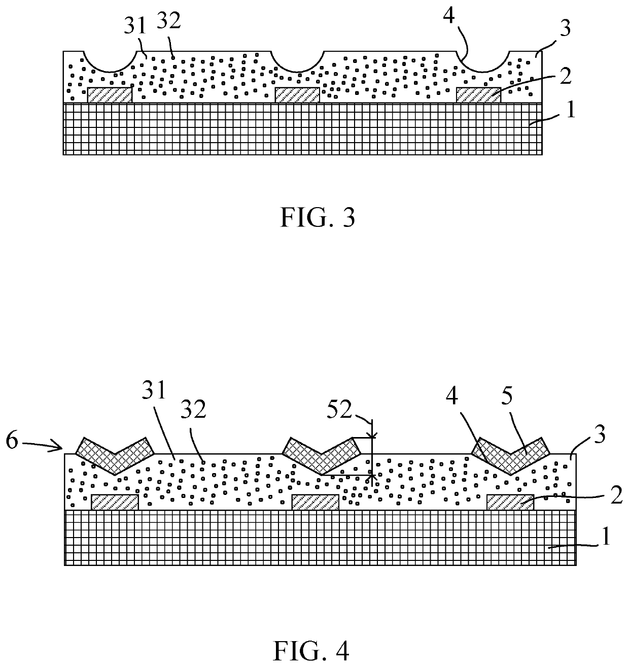
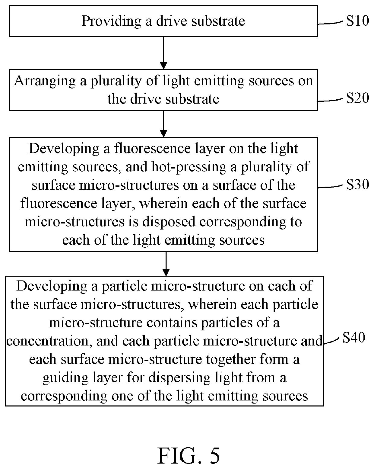
The invention describes a thin backlight module and a manufacturing method that can reduce the thickness of the backlight module while maintaining its efficiency. This is achieved by using surface micro-structures and particle micro-structures on a surface of a fluorescence layer to form a guiding layer for scattering light from a light emitting source. The surface micro-structures are formed by hot pressing and the particle micro-structures, each containing specific concentration of haze particles, are placed on each surface micro-structure by coating or printing. This technology can enhance the diffusion of light, expand the light shape, and reduce the thickness of the backlight module, all while being compatible with conventional LED packaging processes. This invention has advantages such as saving production costs, improving brightness efficiency, and being able to achieve a smaller light mixing distance.

Problems solved by technology

However, the smaller pitch means that a single backlight module needs more mini-LEDs, and consequently production costs increase.
However, when the light mixing distance is shortened to reduce the thickness, the backlight efficiency is also dramatically reduced.
Therefore, it is a challenge to effectively shorten the light mixing distance to achieve requirements for full screens without increasing production costs.
However, when the light mixing distance is shortened to reduce the thickness, the backlight efficiency is also dramatically reduced.
Therefore, it is a challenge to effectively shorten the light mixing distance to achieve requirements for full screens without increasing production costs.

Method used


Image

  • Thin backlight module and manufacturing method thereof
  • Thin backlight module and manufacturing method thereof
  • Thin backlight module and manufacturing method thereof

Examples


Embodiment Construction

[0046]References to “embodiments” in the detailed description mean that the specific features, structures or characteristics described in connection with the embodiments may be included in at least one embodiment of the invention. The same terms mentioned in different places in the specification are not necessarily limited to the same embodiment, but should be understood as independent or alternative embodiments to other embodiments. In view of the technical solutions disclosed in the embodiments of the present invention, those skilled in the art should understand that the embodiments described herein may have other combinations or modifications in accordance with the embodiments of the present invention.

[0047]Embodiments of the present disclosure are described in detail with reference to the accompanying drawings as follows. Directional terms such as up / down, right / left and the like may be used for the purpose of enhancing a reader's understanding about the accompanying drawings, b...


PUM


Abstract

A thin backlight module and a manufacturing method of the thin backlight module are provided. The thin backlight module includes a drive substrate, multiple light emitting sources, a fluorescence layer, and multiple particle micro-structures. The light emitting sources are arranged in an array on the drive substrate. The surface micro-structures are arranged on a surface of the fluorescence layer. Each surface micro-structure is arranged corresponding to each light emitting source. Each particle micro-structure is arranged corresponding to each surface micro-structure. Each particle micro-structure and each surface micro-structure together form a guiding layer for dispersing light from a corresponding one of the light emitting sources. Thereby, a smaller light mixing distance and an ultra-thin backlight module thickness are achieved.

Description

1. FIELD OF DISCLOSURE[0001]The present invention relates to a field of flexible display devices and in particular, to a thin backlight module and a manufacturing method thereof.2. DESCRIPTION OF RELATED ART[0002]Due to the trend toward lighter, thinner, shorter, and smaller electronic products, the concept of thinning has become a main goal that display devices have to continuously work on. Due to the thinning trend, a thickness of the display device is limited, and a thickness of a backlight module is one of the key factors that decides thinness of the display device. LED backlight modules have been widely used in liquid crystal displays. Existing LED backlight modules are mainly categorized into two types, and one of the two types is an edge-lit type and the other is a direct-lit type.[0003]The direct-lit LED backlight module has advantage such as having a narrow bezel, and is widely used in large-size displays, but also increases the thickness. If small-size mini-LEDs are spaced...

Claims


Application Information

Patent Timeline
IPC IPC(8): G02F1/13357G02F1/1335
CPCG02F1/133603G02F1/133614G02F1/133606G02F1/133605G02F1/133609G02F1/133615G02F1/133607
Inventor ZHA, GUOWEI
Owner WUHAN CHINA STAR OPTOELECTRONICS TECH CO LTD
Learn More