
A Supraglottic Airway Device for intermittent Positive Pressure Ventilation

Pending Publication Date: 2021-06-03
SUN YANG
View PDF7 Cites 0 Cited by
  • Summary
  • Abstract
  • Description
  • Claims
  • Application Information

AI Technical Summary

Benefits of technology

The invention is a device for airway management used during positive mechanical ventilation. The device is made of flexible materials that can be easily inserted into a patient's throat without damaging the throat tissues. It has a compressible and elastic air sac with a specific shape that can be compressed during insertion and then expanded during ventilation. The device also includes a bar lifting assembly that can be pushed up to elevate the tongue and a pulling unit that stabilizes the tongue in a raised position. The device has the ability to automatically adjust the amount of airflow based on changes in airflow pressure. The sac bottom wall has air holes that allow the airflow to flow towards the distal end and create a seal with the posterior laryngeal wall. The central thinking area in the sac bottom wall reinforces its rigidity and helps create the seal. Overall, the device helps improve airway management and facilitates ventilation during mechanical ventilation.

Problems solved by technology

Using different type of supraglottic airway devices such as different type of LMAs, I-gel, air-Qsp, Baska mask, laryngeal tube and others for spontaneous ventilation has been widely accepted, but not for mechanical ventilation which can result in significant air leakage to make positive pressure mechanic ventilation ineffective and has other complications.

Method used


Image

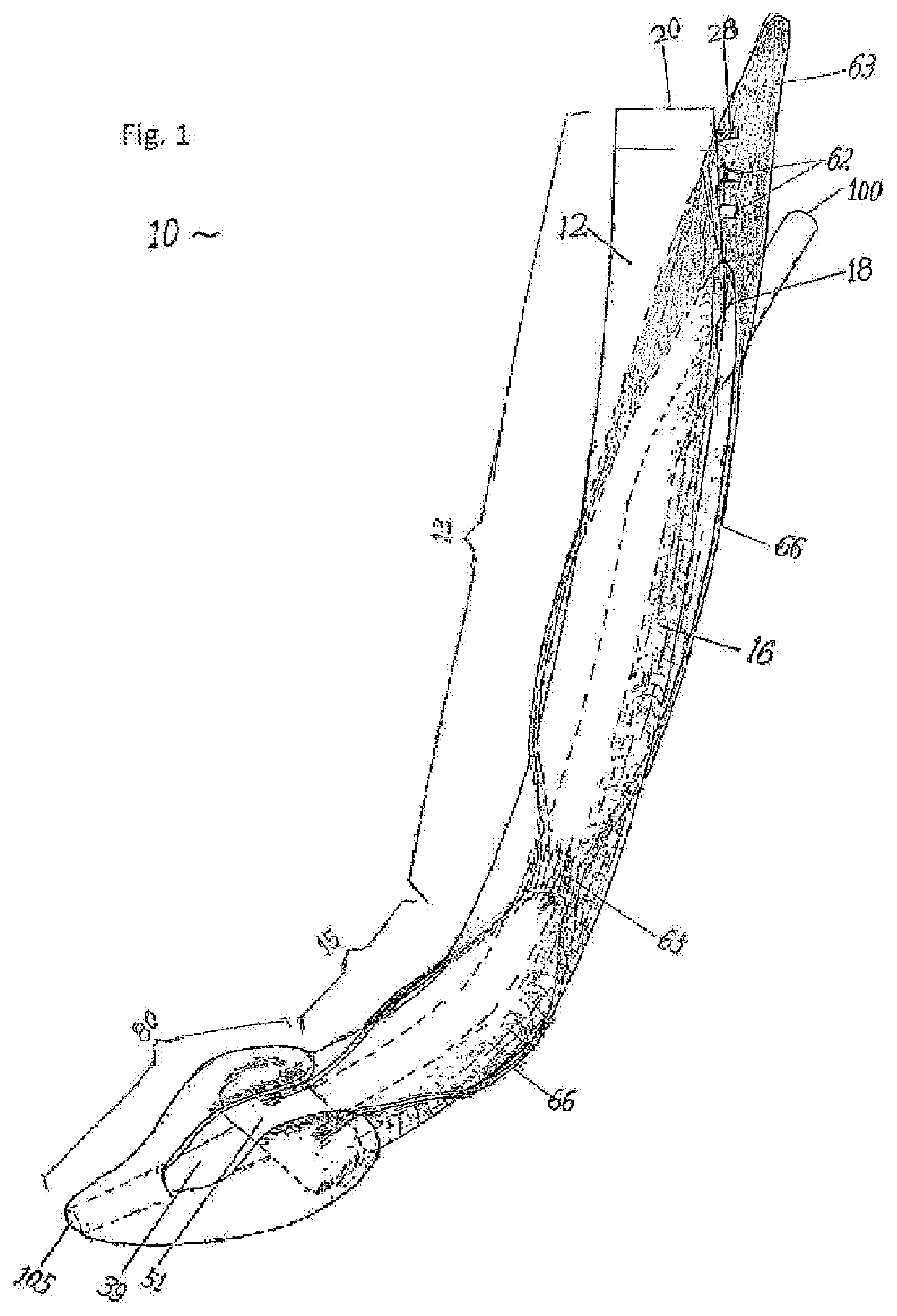
  • A Supraglottic Airway Device for intermittent Positive Pressure Ventilation
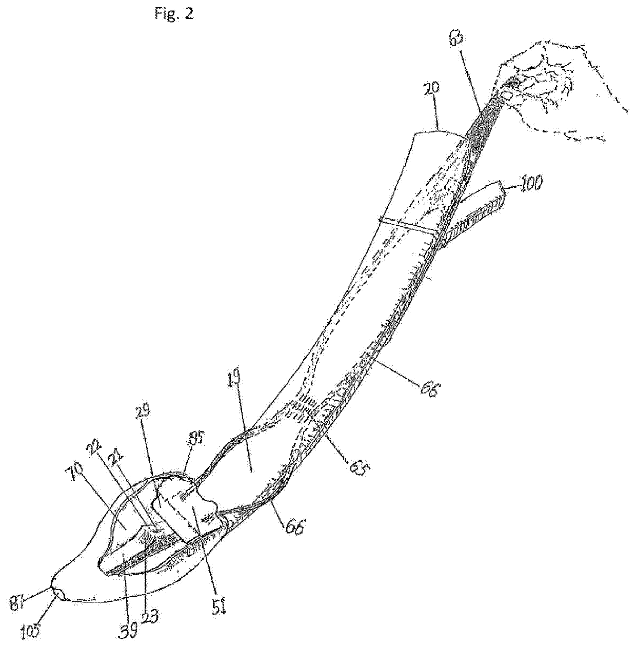
  • A Supraglottic Airway Device for intermittent Positive Pressure Ventilation
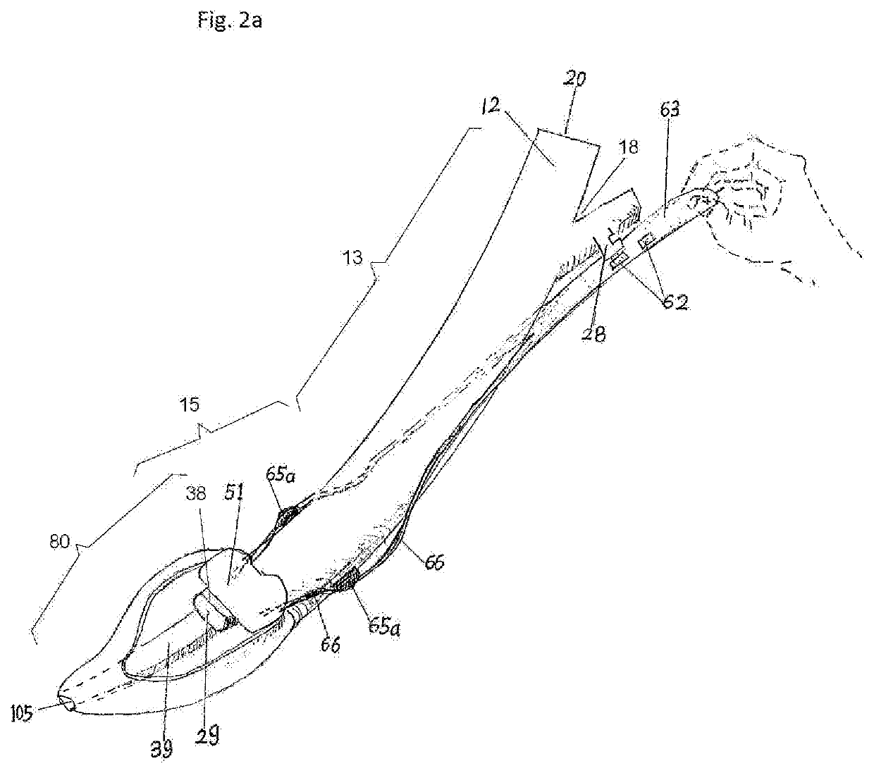
  • A Supraglottic Airway Device for intermittent Positive Pressure Ventilation

Examples


first embodiment

[0102]The first embodiment comprises an air tube, an air sac, a tongue lifting means, and pulling unit 60 with a drainage system, FIG. 1-11, 13.

Air Tube:

[0103]FIG. 1, 2, 3, 4, 5, 6a, 6c, 7a, 7b, 8c, 9a, 9b, 9c, 9d, 10a, 10b, 10c, 11, 11a, 11b1, 11b2, 11c1, 11c2, 11d, 11e, 13, the air tube is a hollow tube includes an air tub proximal segment 13 and an air tube distal segment 15, and is opened at the air tube proximal opening 20 and at air tube distal opening 29, also interchangeably called air tube distal end or edge 29. The air tube 11 can be subjectively divided into an air tube proximal segment 13 and an air tube distal segment 15. Preferably the air tube distal segment 15 is curved anteriorly. The air tube proximal opening 20 is configured to be connected with any currently used respiratory equipment.

[0104]A cross section of outside shape of the air tube can be configured in different geometric shapes. The air tube lumen cross section can be in a circle, semicircle, ellipse, sem...

second embodiment

The Second Embodiment

[0168]In second embodiment, if an element is configured with the same function as in the first embodiment, the same name and number label will be assigned. If an element has same function but configuration is not completely same as in the first embodiment, then a same name but a different number label will be assigned.

[0169]The second embodiment has the same configuration of the tongue lifting means, the pulling unit, and the drainage system as in the first embodiment. But few new alternative designs have been configured, which are a distal airflow tunnel, divergent plate 28a, sac lifting plate 99a, pulling stick 66a, and band anchor 65a. Structures of the upward ramp 22 and the downward ramp 23 have been deleted. The rest of configuration of the air sac will be same as in the first embodiment, FIG. 2a, 3a, 6b, 8a, 8b, 12, 13, 14a, 14b, 14c.

[0170]The air tube outside shape in cross sections in the air tube distal segment 15 is same as in the first embodiment als...

third embodiment

The Third Embodiment

[0195]Same as previously, if an element is configured same with same function as in the first embodiment, the same name and number label will be assigned. If an element has same function but configuration is not completely same as in the first embodiment, then a same name but a different number label will be assigned.

[0196]The third embodiment will comprises an air tube, an air sac, the tongue lifting means and the pulling unit 60 without any drainage tube configuration which will simplify the manufacture process.

[0197]Referring to FIG. 15a, 15b the air tube include an air tube proximal segment 119a and an air tube distal segment 119b and is a hollow tube as no structure inside the air tube lumen 120. Therefore, the outside shape of the air tube is same as inside. The air tube has proximal opening 20 and an air tube distal opening 117 or the air tube distal edge 117. The tongue lifting means and the pulling unit 60 are completely same as in the first and the seco...


PUM


Abstract

An airway device to be inserted into a patient's throat and to be function as a supraglottic airway device during a positive pressure ventilation and spontaneous ventilation that includes an air tube, an air sac, a tongue lifting means, a pulling unit and a drainage systems. The pulling unit will be pulled by an operator's hand to cause the tongue lifting means upward movement to open up the air sac and lift up the tongue base. The air tube lumen and the air sac are configured to have inflow airflow be divided and follow specific route therefore to deliver the focused airflow to vocal cords opening, and also to let inspired airflow enter desired area of the air sac to expand the air sac to form seals with surrounding tissue. During expiration, the pressure will be relieved. Different design of the drainage system can be configured to drained fluid from upper esophagus or from posterior pharyngeal wall.

Description

RELATED APPLICATION[0001]This application is a continuation-in-part of co-pending application Ser. No. 16 / 163,501. The co-pending application Ser. No. 16 / 163,501 filed on Oct. 17, 2018 entitled “A Supraglottic Airway Device for Intermittent Positive Pressure Ventilation” in its entirety is hereby incorporated by reference. Claims 1-15 are based on the Ser. No. 16 / 163,501 patent application and the remaining claims are based on new materials within this application.FIELD OF THE INVENTION[0002]The present invention relates to medical airway management devices and methods that can be used as an independent supraglottic airway device for positive pressure mechanical ventilation and spontaneous ventilation to replace traditional endotracheal intubation in many cases.BACKGROUND OF THE INVENTION[0003]It is standard practice of requiring endotracheal intubation on a patient when positive mechanical ventilation is planned. Using different type of supraglottic airway devices such as different...

Claims


Application Information

Patent Timeline
IPC IPC(8): A61M16/04
CPCA61M16/045A61M16/0447A61M1/008A61M2210/0656A61M2205/0216A61M16/0409A61M16/0463A61M2210/0643A61M16/0488A61M16/0418A61M16/0415A61M16/0431A61M16/0493A61M2205/582A61M2206/11A61M16/0486A61M16/20A61M2205/0222A61B1/2733A61M1/84
Inventor SUN, YANG
Owner SUN YANG
Learn More