
Casting device

Active Publication Date: 2021-05-20
TOYOTA JIDOSHA KK
View PDF0 Cites 0 Cited by
  • Summary
  • Abstract
  • Description
  • Claims
  • Application Information

AI Technical Summary

Benefits of technology

The patent discusses a way to reduce defects in casted products by atomizing the molten metal. This can be done by increasing the speed at which the metal passes through the gate, which causes the metal to become very tiny droplets. This technology improves the quality of the casted product.

Problems solved by technology

However, there is an issue that if the gate speed of the molten metal increases, an amount of heat transferred to a flow path of the molten metal and the mold also increases, which causes erosion and seizure.

Method used


Image

  • Casting device
  • Casting device
  • Casting device

Examples


first embodiment

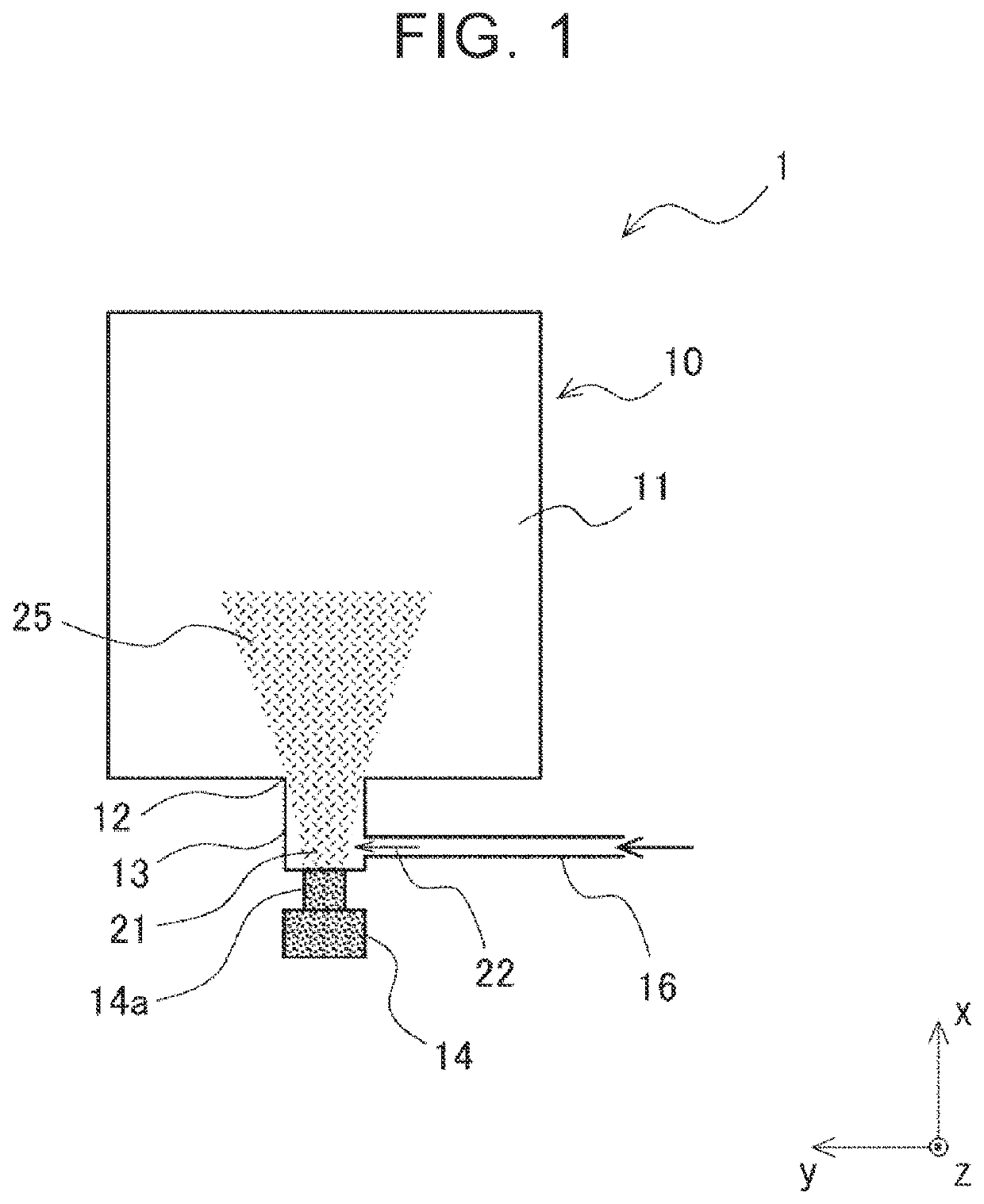
[0022]Hereinafter, an embodiment of the present disclosure will be described with reference to the drawings. FIG. 1 is sectional view for explaining a casting device according to a first embodiment. As shown in FIG. 1, a casting device 1 according to the first embodiment includes a mold 10, a supply path 13, a molten metal supply portion 14, and a gas flow path 16.

[0023]The mold 10 includes a cavity 11 corresponding to a shape of a cast product to be manufactured. For example, the mold 10 includes a fixed mold and a movable mold. The cavity 11 corresponding to the shape of the product is formed inside the mold 10 by coupling the movable mold to the fixed mold and fastening the molds together. A molten metal 25 is then supplied (injected) to the cavity 11 to cast the cast product and the movable mold is separated from the fixed mold to open the mold 10, whereby the cast product is taken out from the mold 10. Subsequently, the cast products can be continuously manufactured by repeatin...

second embodiment

[0044]Next, a second embodiment of the present disclosure will be described. FIG. 4 is a sectional view for explaining a casting device according to the second embodiment. As shown in FIG. 4, a casting device 2 according to the second embodiment includes the mold 10, the supply path 13, the molten metal supply portion 14, and gas flow paths 18a, 18b. Note that, the casting device 2 according to the second embodiment has different configurations of the gas flow paths 18a, 18b, compared to the casting device 1 described in the first embodiment (refer to FIG. 1). The configurations of the casting device 2 other than the gas flow paths are the same as those of the casting device 1 described in the first embodiment. Therefore, the same constituent elements are denoted by the same reference numerals, and redundant description thereof will be omitted.

[0045]As shown in FIG. 4, in the casting device 2 according to the second embodiment, the gas flow paths 18a, 18b are provided so as to conne...


PUM

PropertyMeasurementUnit
Angleaaaaaaaaaa
Shapeaaaaaaaaaa
Areaaaaaaaaaaa

Abstract

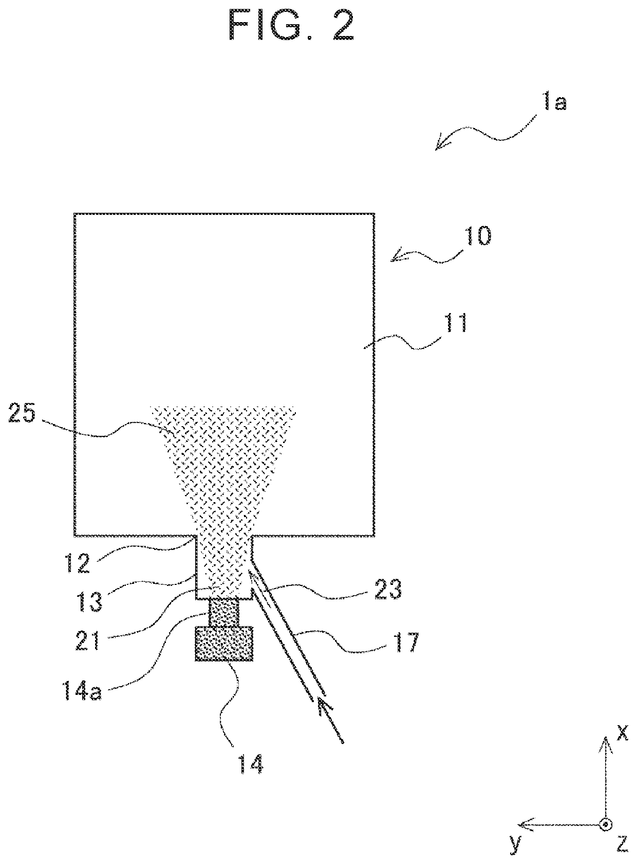
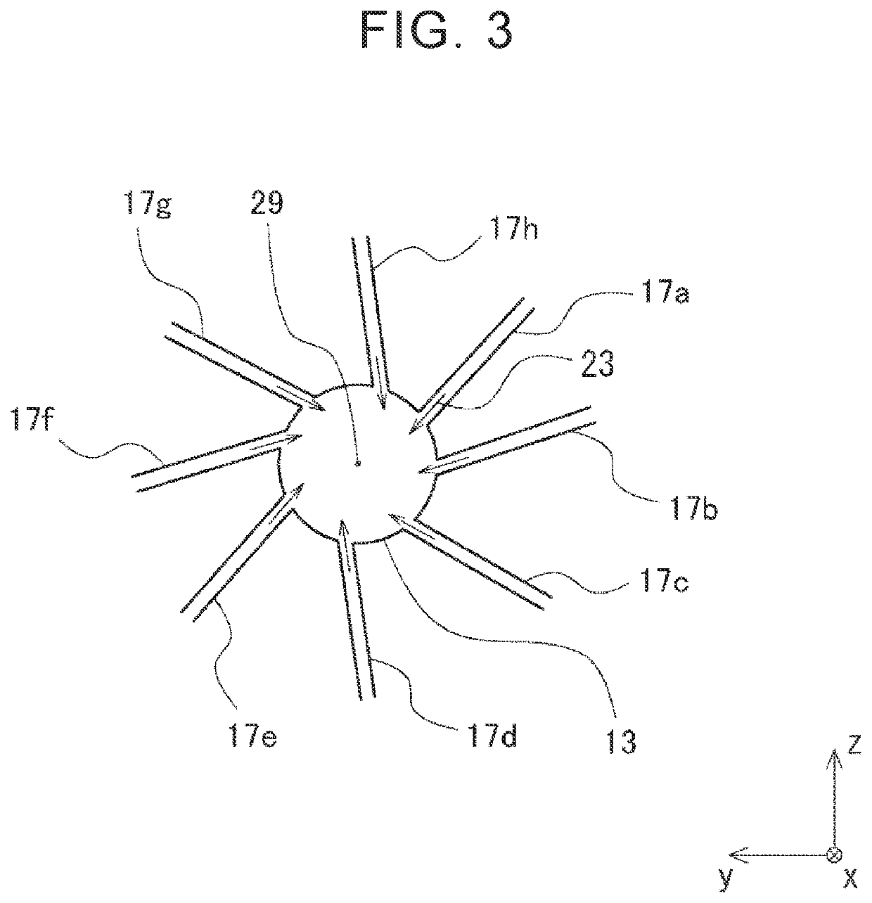
A casting device includes a mold having a cavity, a supply path that is connected to a gate of the cavity and configured to supply a molten metal to the supply path, and a gas flow path that is connected to the supply path and configured to supply a gas to the supply path. In the casting device, a molten metal is atomized by causing the gas supplied from the gas flow path to collide with the molten metal passing through the supply path, and the atomized molten metal is supplied to the cavity.

Description

CROSS-REFERENCE TO RELATED APPLICATION[0001]This application claims priority to Japanese Patent Application No. 2019-207070 filed on Nov. 15, 2019, incorporated herein by reference in its entirety.BACKGROUND1. Technical Field[0002]The present disclosure relates to a casting device.2. Description of Related Art[0003]A casting device is a device that manufactures a cast product by injecting a molten metal into a cavity of a mold. The technical paper JD18-25 presented at the 2018 Japan Die Casting Congress titled “Photography of atomization phenomena in HPDC and development of simulation system for atomized flow by LES-VOF method” discloses that effects such as reduction of an amount of defects in a cast product and improvement of elongation property of the product can be achieved by adopting an atomized flow for the molten metal to be injected into a cavity of the mold. The technical paper JD18-25 presented at the 2018 Japan Die Casting Congress titled “Photography of atomization phen...

Claims


Application Information

Patent Timeline
IPC IPC(8): B22C9/08B22D23/00B22C9/06
CPCB22C9/08B22C9/06B22D23/003B22D17/2015B22D23/00B22C9/108
Inventor ABE, YOSHIKAZUFUJITA, TAKEHISA
Owner TOYOTA JIDOSHA KK
Learn More