
Pouch cell

Pending Publication Date: 2021-05-13
HILTI AG
View PDF0 Cites 1 Cited by
  • Summary
  • Abstract
  • Description
  • Claims
  • Application Information

AI Technical Summary

Benefits of technology

The present invention provides a rechargeable battery pack with increased operational safety. The battery pack has a control circuit that interrupts or reduces current when a sensor detects damage to the battery, such as a severed filament. This helps protect the remaining pouch cells in the battery pack. The battery pack also has a signal element, like an LED, indicating damage to the pouch cell, allowing for replacement in a timely manner. A heat-conducting plate or volume-compensation plate can be used to dissipate heat and compensate for swelling of the battery pack.

Problems solved by technology

This is problematic since it can lead to an outer cover of the pouch cell bursting open.

Method used


Image

  • Pouch cell
  • Pouch cell
  • Pouch cell

Examples


Embodiment Construction

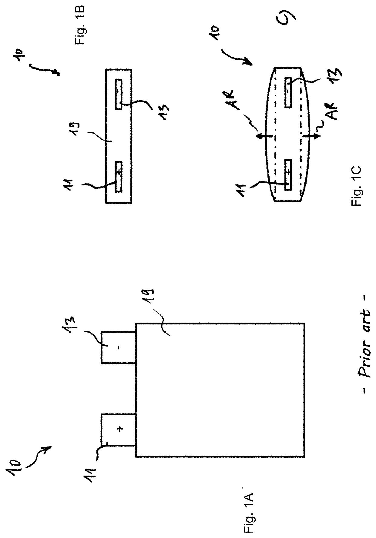
[0030]A pouch cell of the prior art is illustrated in FIGS. 1A, 1B and 1C showing a pouch cell 10 having a planar housing 19 of flat design. The pouch cell 10 has a metal positive contact 11 and a metal negative contact 13. The pouch cell 10 can be electrically contacted and thereby charged and discharged via the positive contact 11 and the negative contact 13.

[0031]FIG. 1A shows a plan view of the pouch cell 10. FIG. 2B shows the side view of the pouch cell 10 of FIG. 1A. The pouch cell 10 of FIG. 1B is a new pouch cell, that is to say expansion of the pouch cell 10 has not yet started. In contrast to this, FIG. 1C shows an aged, expanded pouch cell. Said pouch cell has expanded on both sides in the expansion direction AR.

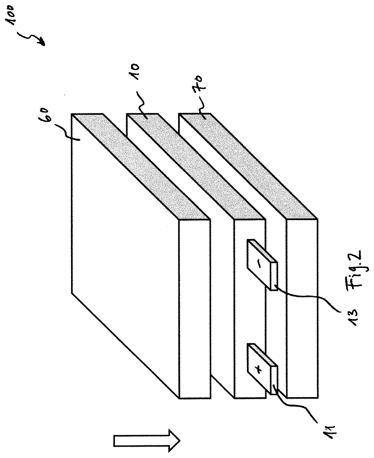
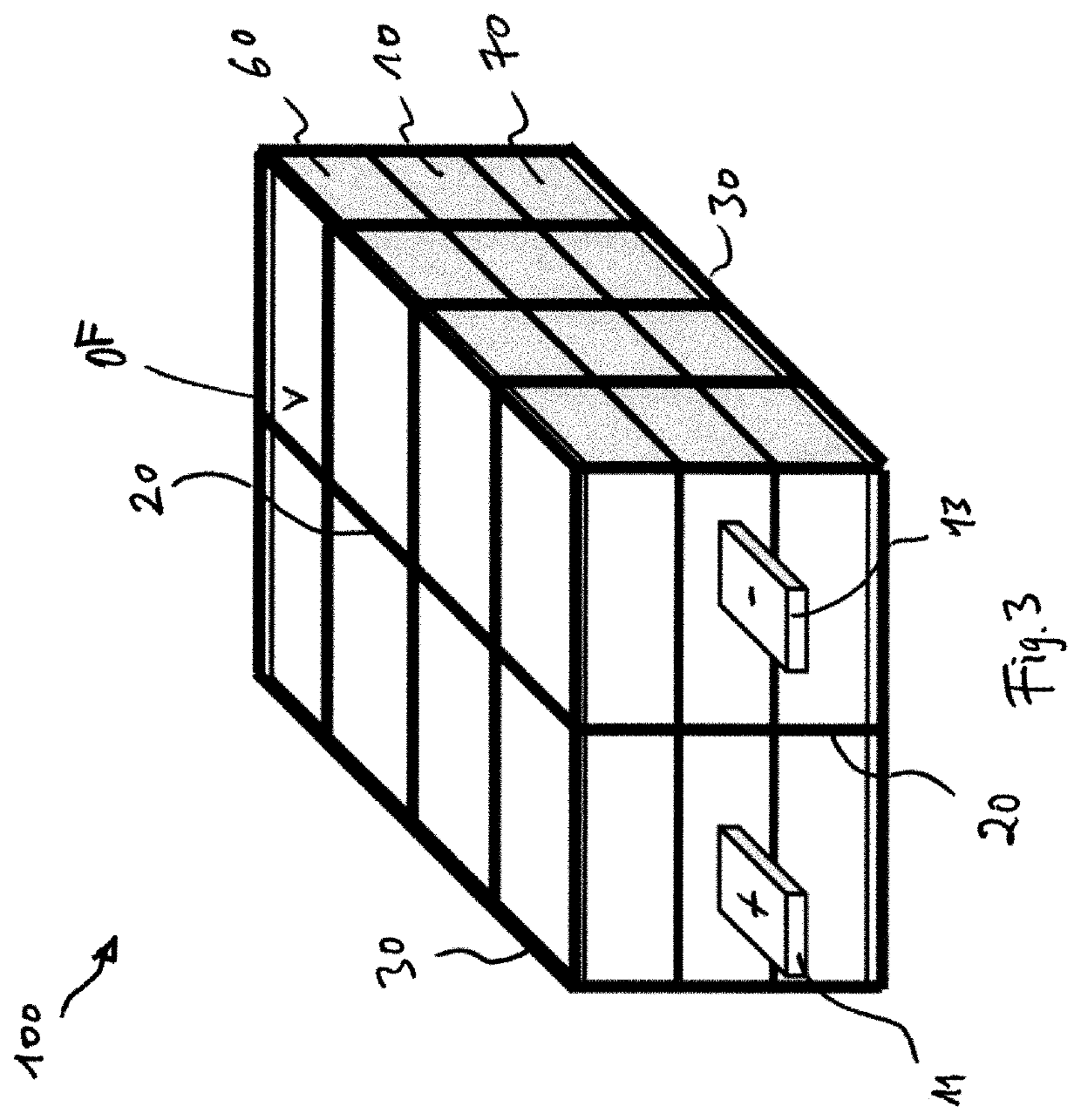
[0032]FIG. 2 shows the design of a rechargeable battery pack according to the invention, but in the first instance without the electrically conductive filament 20 provided according to the invention (cf. FIG. 3).

[0033]The rechargeable battery pack 100 of FIG. 2 ha...


PUM


Abstract

A rechargeable battery pack having at least one pouch cell, wherein the rechargeable battery pack has at least one electrically conductive filament which surrounds the pouch cell at least in sections in such a way that expansion of the pouch cell causes severing of the filament.

Description

[0001]The present invention relates to a rechargeable battery pack having at least one pouch cell.BACKGROUND[0002]Rechargeable battery packs and pouch cells are known in principle from the prior art. The phenomenon of what is known as swelling, also referred to as expansion, is likewise known from the prior art. This is problematic since it can lead to an outer cover of the pouch cell bursting open.SUMMARY OF THE INVENTION[0003]It is an object of the present invention to provide a rechargeable battery pack that provides the basis for increased operational safety.[0004]The present invention provides that the rechargeable battery pack has at least one electrically conductive filament which surrounds or delimits the pouch cell at least in sections in such a way that expansion of the pouch cell causes severing of the filament.[0005]The filament provided according to the invention creates the basis for an effective detection or monitoring system by means of which swelling of one or more ...

Claims


Application Information

Patent Timeline
IPC IPC(8): H01M50/583H01M50/211H01M50/247H01M10/48H01M50/244H01M10/617H01M10/6235H01M10/647H01M10/6555B25F5/00H01M50/202H01M50/242
CPCH01M50/583H01M50/211H01M50/247H01M10/488H01M10/482H01M50/244H01M2200/103H01M10/6235H01M10/647H01M10/6555B25F5/00H01M2220/30H01M10/617Y02E60/10H01M50/578H01M50/202H01M50/242
Inventor LEPIORZ, MATTHIASENDER, MOSESSTANGER, ROBERT
Owner HILTI AG
Learn More