
Self-service device

Active Publication Date: 2013-10-22
DIEBOLD NIXDORF SYST GMBH
View PDF20 Cites 0 Cited by
  • Summary
  • Abstract
  • Description
  • Claims
  • Application Information

AI Technical Summary

Benefits of technology

The invention is a system for protecting the security and functionality of a self-service device. It includes a functional strip that can be attached to the operating panel and cover surface of the device. The functional strip has visual protection measures and an elevated position relative to the cover surface, making it easier to detect unauthorized installations. It also has a continuous tapering shape to provide a visually attractive appearance and act as a guide surface for sheet-shaped objects. The technical effects of the invention are improved security and protection of the self-service device from unauthorized installation.

Problems solved by technology

However, the sensor unit requires the placement of sensors above a plane of extension of the operating panel, which is undesirable with respect to the risk of vandalism.
The disadvantage of the known self-service device is that when attaching the security element to the cover surface an adjustment must be undertaken regarding the type of attachment or the location of the attachment of the operating unit itself to the cover surface.

Method used


Image

  • Self-service device
  • Self-service device
  • Self-service device

Examples


first embodiment

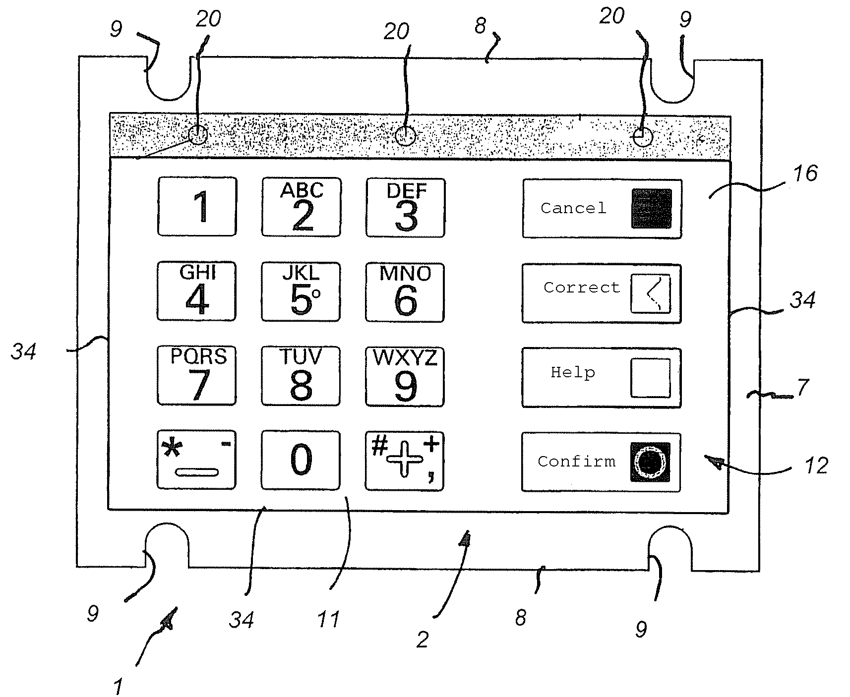
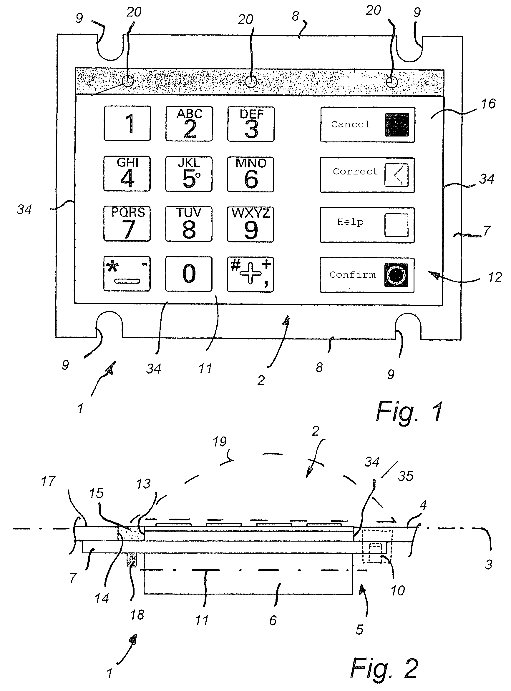
[0029]In accordance with the invention, a functional strip 15, rectangular in cross-section, extends in an intermediate space between a longitudinal first edge 13 of the operating panel 2 and a longitudinal first edge 14 of the recess 9. The functional strip 15 is of a thickness that it runs flush with an adjacent upper side 16 of the operating panel 2 and an upper side 17 of the cover surface 4. The functional strip 15 is attached by a positive-locking and / or interference-fit connection or is materially bonded to the mounting frame 7. In the present embodiment, the functional strip 15 is connected by a threaded fastener 18 to the mounting frame 7.

[0030]The functional strip 15 contains holes 20 disposed distributed in the lengthwise direction of the functional strip 15 as retaining means to anchor a visual protection element 19 to said strip. The holes 20 can have an internal thread so that the dome-shaped visual protection element 19 can be attached to the functional strip 15 by th...

third embodiment

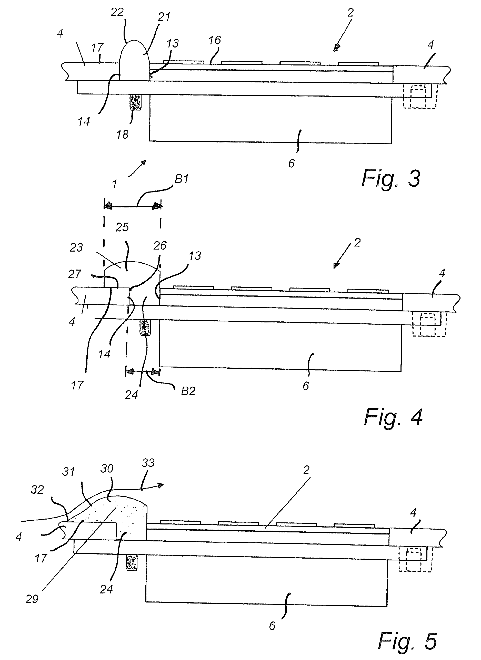
[0040]In accordance with a further embodiment of the invention in accordance with FIG. 5, a functional strip 29 can be provided that, in contrast to the functional strip 23 tapers off constantly at an upper second leg 30 toward the upper side 17 of the cover surface 4. The second leg 30 of the functional strip 29 has an upper side 31 whose edge 32 facing away from the operating panel 2 comes immediately to rest on the upper side 17 of the cover surface 4. Advantageously, the upper side 31 can act as a guide surface for paper valuables that are dispensed via an adjacent dispensing slot in the housing, as is indicated by the arrow 33.

[0041]The operating panel 2 has additional edges 34 next to the first edge 13 that abut immediately against matching edges 35 of the cover surface 4. In this area the upper side 16 of the operating panel 2 runs flush with the upper side 17 of the cover surface 4.


PUM


Abstract

A self-service device, particularly an automated cash machine, having an operating unit with an operating panel for entering alphanumeric characters and / or control data, and having a cover surface having a plurality of edges bounding a recess, whereby the operating panel is encompassed, wherein at least one first edge of the cover surface is disposed at a distance from a first edge of the operating panel, forming an intermediate space, wherein a functional strip is disposed, the functional strip being mounted on a mounting frame encompassing the operating panel, said frame being connected to the cover surface by mounting elements.

Description

CROSS-REFERENCE TO RELATED APPLICATIONS[0001]This application is a National Stage of International Application No. PCT / EP2009 / 001118, filed Feb. 18, 2009. This application claims the benefit and priority of German application 10 2008 014 324.3 filed Mar. 14, 2008. The entire disclosures of the above applications are incorporated herein by reference.BACKGROUND[0002]This section provides background information related to the present disclosure which is not necessarily prior art.[0003]1. Technical Field[0004]The invention relates to a self-service device, particularly an automated cash machine, having an operating unit comprising an operating panel for entering alphanumeric characters and / or control data and having a cover surface having a plurality of edges bounding a recess, whereby the operating panel is encompassed.[0005]2. Discussion[0006]A self-service device is known from DE 197 39 771 A1 comprising an operating unit having an operating panel for entering alphanumeric characters...

Claims


Application Information

Patent Timeline
IPC IPC(8): G07F19/00G06K5/00G06F7/08
CPCG07F19/20G07F19/201G07F19/205
Inventor BLECK, FRANKGOLUEKE, PETER
Owner DIEBOLD NIXDORF SYST GMBH
Learn More