
Multi-beam measuring device with high directional stability for 3D scanning of an environment

Pending Publication Date: 2021-05-13
HEXAGON TECH CENT GMBH
View PDF0 Cites 0 Cited by
  • Summary
  • Abstract
  • Description
  • Claims
  • Application Information

AI Technical Summary

Benefits of technology

The patent is about improving the accuracy of a 3D scanning device that uses multiple channels for transmitting and receiving signals. The goal is to make it easier to identify and locate objects within the environment being scanned.

Problems solved by technology

The hysteresis of the turning beams is very small.

Method used


Image

  • Multi-beam measuring device with high directional stability for 3D scanning of an environment
  • Multi-beam measuring device with high directional stability for 3D scanning of an environment
  • Multi-beam measuring device with high directional stability for 3D scanning of an environment

Examples


Embodiment Construction

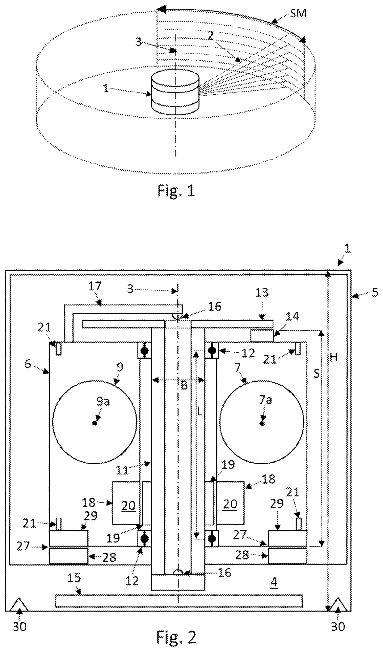
[0043]FIG. 1 shows a measuring device 1 transmitting transmission beams 2 wherein transmission beams 2 are rotated about an axis of rotation 3. During rotation every transmission beam 2 is moving over a conical surface, a light cone, wherein all light cones have the axis of rotation 3 as common cone axis. In continuous mode of operation, the frequency of rotation is uniform and can be set between 0.5 Hz and 300 Hz. The scanned field of view covers a horizontal angle of 360 deg and a vertical angle of typically 40 deg. Depending on the morphological configuration of the instrument, the vertical angle can be extended to 150 deg. In addition to the continuous mode, a sweeping mode SM can be applied, wherein the horizontal field of view or the scan region, respectively, is typically 120 deg or less depending on the settings of the motor controller. In this sweeping mode SM a section of the surrounding, for example a scene in forward direction of a moving measuring device 1 is scanned in...


PUM


Abstract

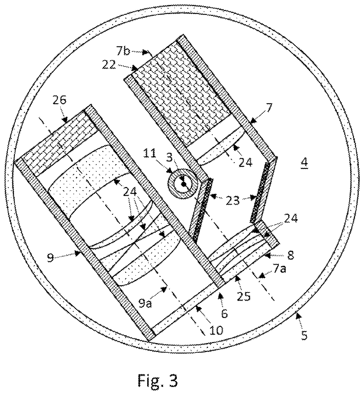
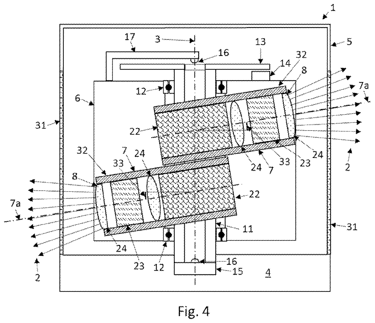
A measuring device comprises a base, a case, and a rotating member rotatable about the axis of rotation. The rotating member comprises a transmission unit configured to emit transmission beams to different beam directions. The rotating member further comprises a receiver unit configured to receive returning transmission beams. A longitudinal member is fixed to the base and extends in a central area of the rotating member along the axis of rotation over a range including the transmission unit and the receiver unit. Two bearing members are arranged on the longitudinal member and on the rotating member. In the direction of the axis of rotation, the transmission unit and the receiver unit are located in a range between the two bearing members. The measuring device has a high aiming accuracy and low hysteresis of the turning transmission beams.

Description

CROSS-REFERENCE TO RELATED APPLICATIONS[0001]This application claims priority to European Patent Application No. 19208687.4, filed on Nov. 12, 2019. The foregoing patent application are incorporated herein by reference.FIELD OF INVENTION[0002]The invention concerns a measuring device for three-dimensional (3D) scanning of an environment using multiple transmission and reception channels.BACKGROUND[0003]Methods for the detection of objects or surfaces in an environment often perform a scanning by means of one or multiple distance measuring beams, e.g. pulsed modulated laser beams of a laser scanning device. The spatial positions of surface points are determined by the laser by measuring the distance to the targeted surface point and linking this measurement with position and angle information of the laser transmission. This position, angle and distance information is used to determine the spatial positions of measured points and, for example, to create a so-called 3D point cloud. Dir...

Claims


Application Information

Patent Timeline
IPC IPC(8): G01S7/481G01S17/894G01S17/42
CPCG01S7/4817G01S17/42G01S17/894G01S17/89G01S7/4815G01S7/4816
Inventor WOHLGENANNT, RAINERHINDERLING, JÜRGBESTLER, SIMON
Owner HEXAGON TECH CENT GMBH
Learn More