
Configurable form system for fabricating precast panels

a prefabricated panel and form system technology, applied in the direction of form/shutter/falsework, shaping building parts, mould fastening means, etc., can solve the problems of requiring continued replacement cost, affecting the quality of prefabricated parts, and requiring unnecessary man-hours to erect, so as to reduce the cost of fabricating, prevent heavy moisture absorption, and reduce the effect of cumbersomeness

Inactive Publication Date: 2021-05-13
MW PANEL TECH LLC
View PDF24 Cites 3 Cited by
  • Summary
  • Abstract
  • Description
  • Claims
  • Application Information

AI Technical Summary

Benefits of technology

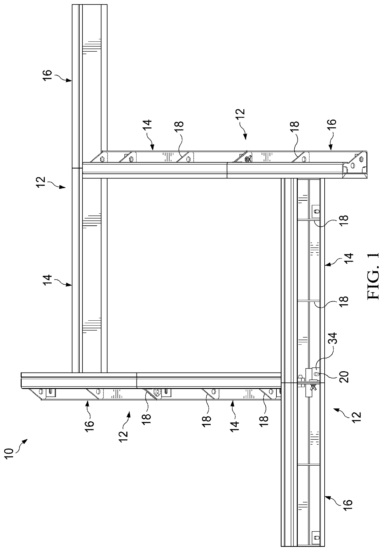
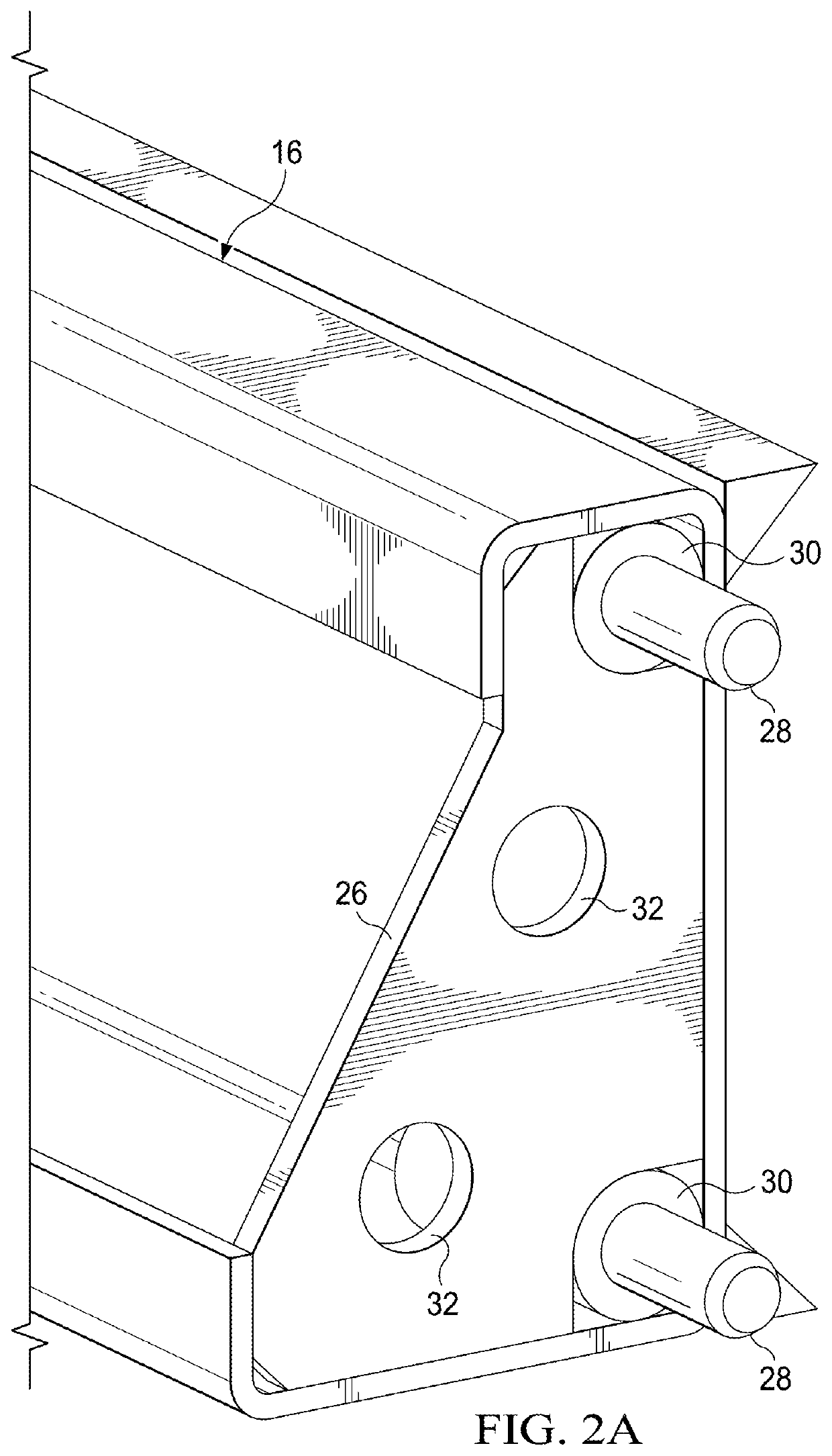
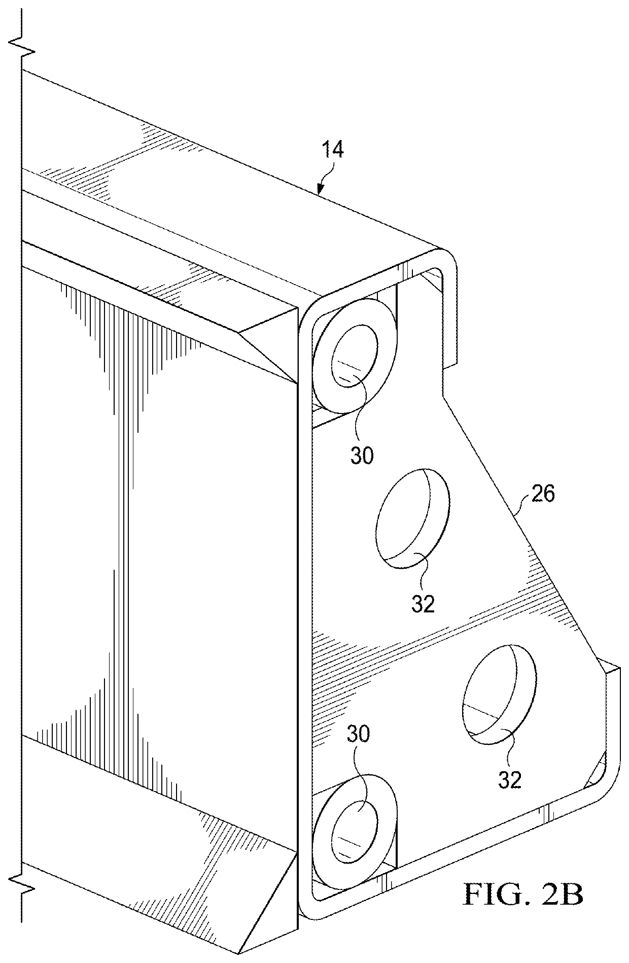
The present invention provides a configurable form system for creating precast concrete panels that can be used for various applications such as commercial tilt panels and highway noise barrier walls. The modular form system is made up of steel form system sections that can be quickly assembled with connectors to extend the length of a section. Each section has the panel depth and contour fabricated into the steel form profile, and also includes anchoring slots and corner miters. The system can be coupled with shoring apparatuses to facilitate the fabrication of panels. The use of lighter materials such as high-density polyethylene for the chamfers enables the creation of panels with beveled edges and removably engage an end of a section with a chamfered-side of another section. The shoring apparatuses described herein provide advantages over frameworks known in the art, reducing cost and heavy absorption of moisture that can lead to warping. Various design customizations can be incorporated into the shoring apparatuses, providing flexibility for different types of panels. The shoring apparatuses can be easily fabricated and incorporating customizations is easy.

Problems solved by technology

Due to the difficulty and expense associated with transporting the concrete panels from a fabrication facility to a worksite, the concrete panels are generally fabricated at the worksite.
Conventional approaches generally suffer from the same drawbacks: they are wasteful, require unnecessary man-hours to erect, and require continued replacement cost.
However the wood can warp and produce uneven surface in a resulting concrete panel.
The combination of concrete and wood results in problems.
As wood is not rigid, the wooden framework also requires bracing, typically every twelve inches, to support the framework, resulting in additional expense.
The wooden edges of the framework are also prone to chip.
The complexity and manpower required to construct this wooden framework (cutting individual components, bracing the pieces, and fastening the components together) coupled with the extra equipment required to form such components, results in wasted man-hours and greater expense, to create a flawed product.
Other approaches include the use of aluminum frameworks, but such frameworks are expensive and subject to work site theft due to their expense.
Reuse is similarly difficult, with the added burden of dismantling the aluminum framework to remove the concrete panel, removing the bolts, and cleaning the components with a wire brush to remove the concrete residue.
Additionally, varying panel thickness using these traditional frameworks is very difficult; generally, a new framework of a different height will need to be fabricated in order to change the panel thickness, requiring significant time and effort to construct and install.

Method used


Image

  • Configurable form system for fabricating precast panels
  • Configurable form system for fabricating precast panels
  • Configurable form system for fabricating precast panels

Examples


Embodiment Construction

[0031]The preferred version of the invention presented in the following written description and the various features and advantageous details thereof are explained more fully with reference to the non-limiting examples included in the accompanying drawings and as detailed in the description which follows. Descriptions of well-known components and processes and manufacturing techniques are omitted so as to not unnecessarily obscure the principle features of the invention as described herein. The examples used in the description which follows are intended merely to facilitate an understanding of ways in which the invention may be practiced and to further enable those skilled in the art to practice the invention. Accordingly, the examples should not be construed as limiting the scope of the claimed invention.

[0032]FIG. 1 is a perspective view of a configurable steel form system, designated generally as 10, in accordance with an embodiment of the present invention. The configurable stee...


PUM


Abstract

A configurable form system for creating precast concrete panels is disclosed. The configurable form system can be used to create precast panels for both commercial tilt panels and highway noise barrier walls, among other applications. A plurality of form system sections are preferably fabricated from steel plate bent into a J-channel member. The configurable form system can be designed in sections that are quickly assembled. To suit a particular application, a section can be extended by sequentially attaching extension members to a primary member. A plurality or faces or shoring apparatuses can be coupled to the section to circumscribe or form an inner diameter of an enclosure formed by the sections. The shoring apparatuses can vary in height, allowing for fabrication of panels of variable thickness using the same forms or framework. The shoring apparatuses can be configured to removably engage ends of sections to facilitate the formation of enclosures using the sections.

Description

CROSS REFERENCE TO RELATED APPLICATIONS[0001]This application is a Continuation-in-Part of U.S. application Ser. No. 16 / 123,744, filed Sep. 6, 2018, the entirety of which is incorporated herein by reference. This application hereby cross-references U.S. application Ser. No. 17 / 110,540 filed Dec. 11, 2020, and PCT Application Serial No. PCT / US19 / 49017 filed Nov. 21, 2019, the entireties of which are incorporated herein by reference.BACKGROUNDField of the Invention[0002]The present invention is generally related to steel form systems, and more specifically to systems and methods for creating configurable precast concrete panels.Background of the Invention and Description of Related Art[0003]Concrete panels have long been used in commercial construction projects. Due to the difficulty and expense associated with transporting the concrete panels from a fabrication facility to a worksite, the concrete panels are generally fabricated at the worksite. Conventional approaches generally suff...

Claims


Application Information

Patent Timeline
Patent Type & Authority Applications(United States)
IPC IPC(8): E04G17/04E04G11/08
CPCE04G17/042E04G11/08B28B7/0014B28B7/0017B28B7/0026
Inventor WHITE, JONATHAN
Owner MW PANEL TECH LLC
Learn More