Sliding bearing pad support
- Summary
- Abstract
- Description
- Claims
- Application Information
AI Technical Summary
Benefits of technology
Problems solved by technology
Method used
Image
Examples
Embodiment Construction
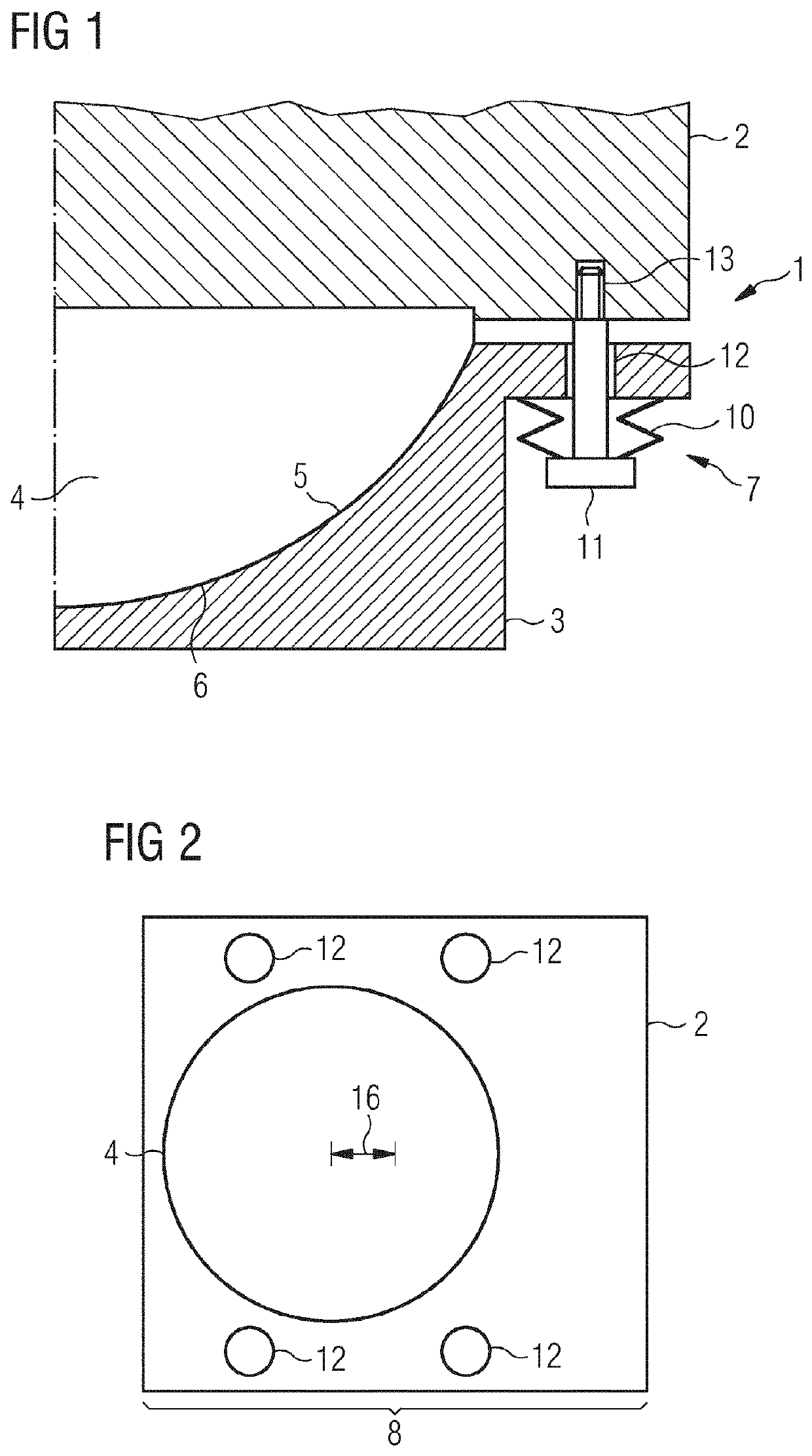
[0082]FIG. 1 shows a bearing pad support connection.
[0083]FIG. 1 shows a bearing pad support connection 1, the bearing pad 2 is connected to a support structure 3.
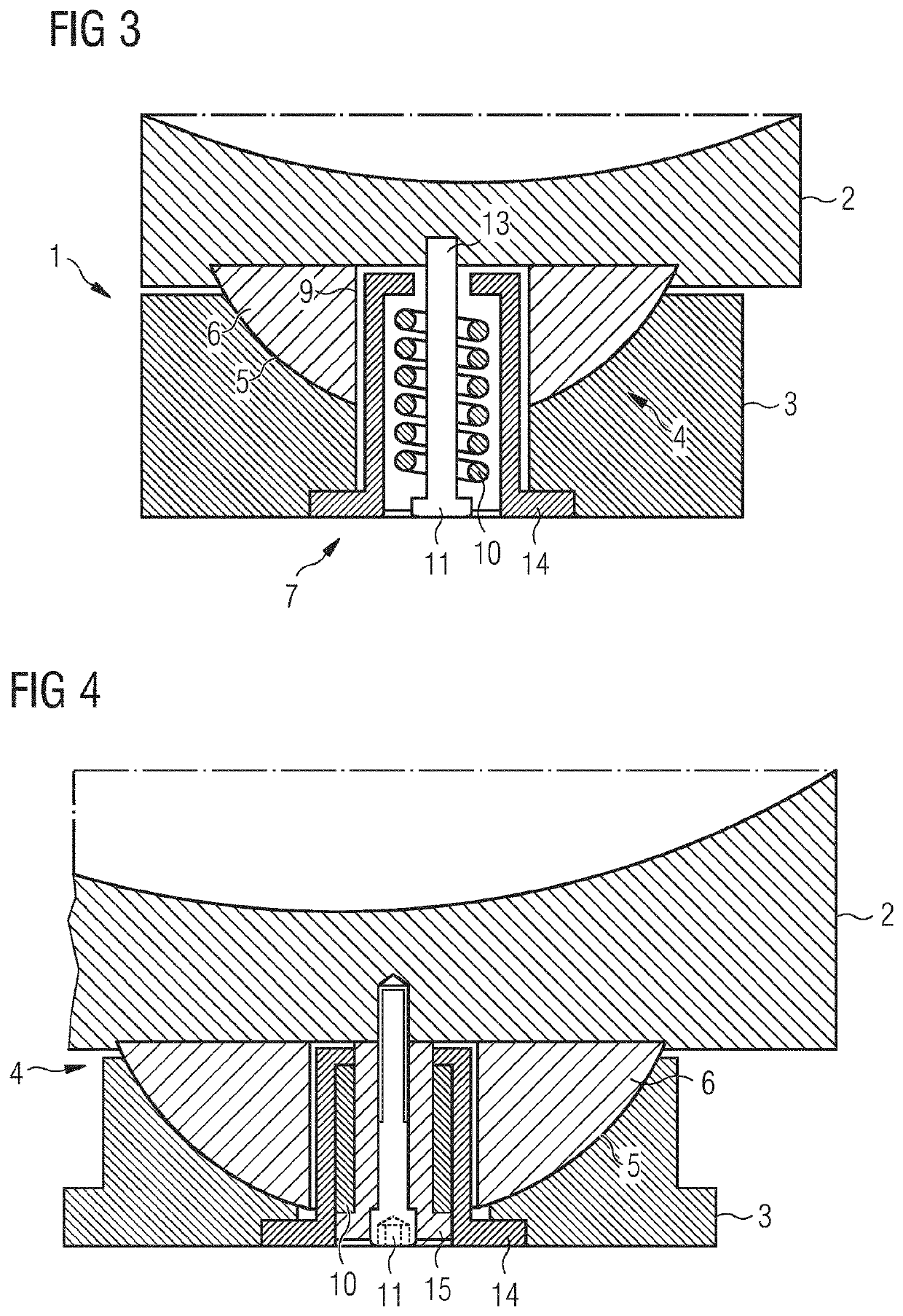
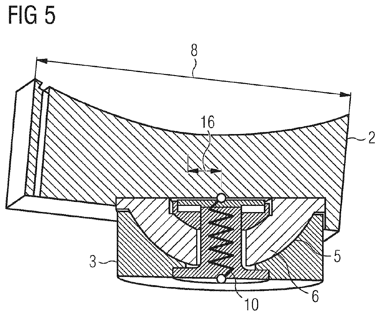
[0084]The bearing pad 2 is connected to the support structure 3 by a ball joint 4. The bearing pad 2 comprises a ball head 6, and a support structure 3 comprises a ball socket 5.
[0085]The bearing pad 2 is connected to the support structure 3 by a spring connection 7. The spring connection 7 comprises a bolt 11 and a spring 10.
[0086]The support structure 3 comprises a bolt hole 12, and the bearing pad 2 comprises a thread 13. The bolt 11 is leading through the bolt hole 12 to the thread 13 in the bearing pad 2.
[0087]The spring 10 is arranged between the head of the bolt 11 and the support structure 3 to apply a force to the head of the bolt 11 to force the head of the bolt 11 away from the support structure 3. The force of the spring 10 is transferred by the bolt 11 to the bearing pad 2. Thus, a force is applied between the...
PUM
 Abstract
Description
Claims
Application Information
 - R&D Engineer
- R&D Manager
- IP Professional
- Industry Leading Data Capabilities
- Powerful AI technology
- Patent DNA Extraction
Browse by: Latest US Patents, China's latest patents, Technical Efficacy Thesaurus, Application Domain, Technology Topic, Popular Technical Reports.
© 2024 PatSnap. All rights reserved.Legal|Privacy policy|Modern Slavery Act Transparency Statement|Sitemap|About US| Contact US: help@patsnap.com


