
Rim, rim component and rim assembly for a bicycle wheel and methods of manufacture thereof

a technology of rims and bicycle wheels, which is applied in the direction of spoked wheels, bicycles, transportation and packaging, etc., can solve the problems of negating any improvement in rolling resistance, increasing aerodynamic drag, and affecting so as to achieve easy control of the bonding of pre-preg sheets to each other, and increase the flexibility of positioning of such a rim component. , to achieve the effect of restoring the strength and integrity of the rim

Pending Publication Date: 2021-05-06
ITS CYCLING LTD
View PDF0 Cites 1 Cited by
  • Summary
  • Abstract
  • Description
  • Claims
  • Application Information

AI Technical Summary

Benefits of technology

The invention is a rim assembly comprising a rim and a rim component. The rim component has a lower density than the rim, making the entire assembly lighter than a rim without a rim component. This is especially useful for manufacturing wider rims that require thicker wall sections. The rim assembly allows for creating wider rims with minimal weight penalty. A layer of protective material can be applied to the external surface of the rim assembly to protect it from damage. The technical effect is that the invention allows for creating rims with improved aerodynamic and handling performance.

Problems solved by technology

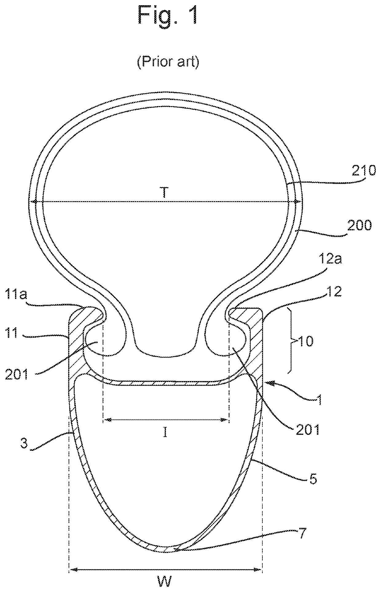
This “light bulb” shape adopted by the mounted tyre causes both aerodynamic and handling issues.
Firstly, as the width of the tyre T is substantially greater than the outer width of the rim W, this causes an increase in aerodynamic drag which negates any improvements in rolling resistance gained by using a wider tyre.
Secondly, the “bulging” of the tyre with respect to the rim can cause lateral movement of the tyre during use, especially when cornering, leading to adverse handling characteristics.
However, this necessarily requires thicker wall sections of the rim, particularly in the tyre-mounting portion of the rim.
Thicker wall sections require the use of an increased amount of material in manufacturing the rim, leading to heavier rims.
Heavier rims are particularly undesirable due to the increased rotational moment of inertia of the final bicycle wheel, which can cause sluggish acceleration and reduced performance.

Method used


Image

  • Rim, rim component and rim assembly for a bicycle wheel and methods of manufacture thereof
  • Rim, rim component and rim assembly for a bicycle wheel and methods of manufacture thereof
  • Rim, rim component and rim assembly for a bicycle wheel and methods of manufacture thereof

Examples


Embodiment Construction

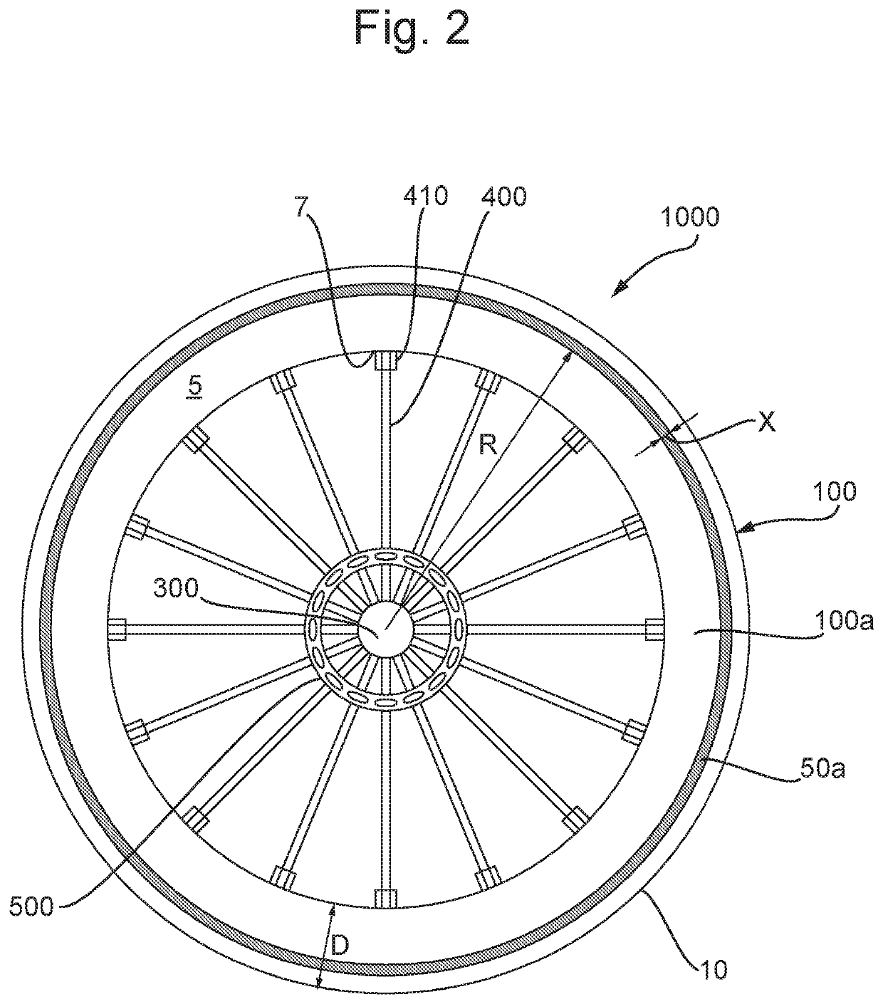
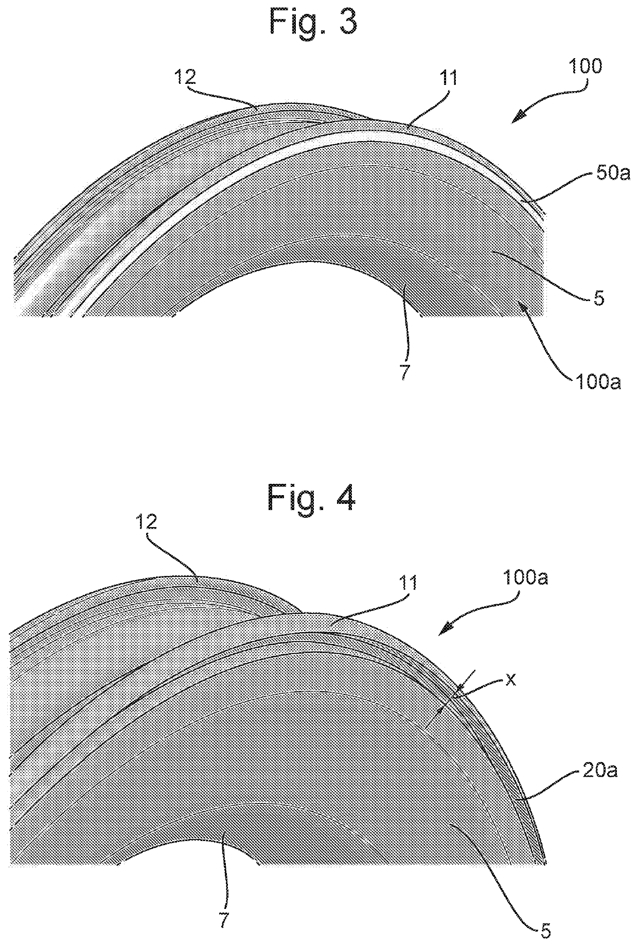
[0093]FIG. 2 is a schematic side view of a bicycle wheel 1000 comprising a rim assembly 100, the rim assembly being according to an embodiment of the present invention. The rim assembly 100 comprises a rim 100a and an insertable rim component 50a located in an external surface of the rim 100 such that the rim component 50a forms part of the external surface of the rim. For ease of description, the insertable rim component may simply be referred to as an “insert” in the remainder of the description.

[0094]The wheel 1000 is shown without a tyre mounted on it. As can be seen, the rim 100a is substantially annular in shape, and has a depth “D” which is the distance between the radially inner and radially outer portions of the rim. A tyre (which could be a clincher tyre, tubular tyre or tubeless tyre) is mounted to the radially outer tyre-mounting portion 10 of the rim.

[0095]The wheel also comprises a hub 300 and a plurality of spokes 400 (typically between 16 and 36) connecting the hub t...


PUM

PropertyMeasurementUnit
Lengthaaaaaaaaaa
Lengthaaaaaaaaaa
Widthaaaaaaaaaa

Abstract

A rim assembly for a bicycle wheel is disclosed. The rim assembly comprises: a rim configured to receive a rim component in an external surface thereof, and; a rim component located in the external surface of the rim, wherein the rim component forms part of the external surface of the rim, and wherein; the rim component has a lower density than the rim. A rim, insertable rim component and methods of manufacturing such a rim assembly are also disclosed.

Description

FIELD OF THE INVENTION[0001]This invention relates to a rim and rim assembly for a bicycle wheel and associated methods of manufacture. The invention also relates to a wheel for a bicycle.BACKGROUND TO THE INVENTION[0002]A traditional bicycle wheel comprises a rim, a hub and a plurality of spokes, with the spokes connecting the hub to the rim. A bicycle tyre is mounted to the rim, using either a clincher, tubular or tubeless configuration. The wheel is mounted to a bicycle frame at the hub.[0003]A recent focus in wheel rim technology concerns aerodynamic efficiency, with the shape of the rim affecting the flow of air over its surface. More specifically, the focus has been directed to the combination of the rim and the mounted tyre, with efforts being made to reduce the aerodynamic drag resulting from the combination of the rim and tyre, therefore allowing riders to maintain higher speeds.[0004]FIG. 1 is a schematic cross section of a traditional rim for a bicycle wheel. The rim 1 is...

Claims


Application Information

Patent Timeline
IPC IPC(8): B60B21/02B60B21/06
CPCB60B21/025B60B21/04B60B21/062B60B2360/00B60B21/106B60B21/12B60Y2200/13B60B7/01B60B21/00B60B1/00B60B5/00B60B7/00B60B21/026B60B2360/3416B60B2360/346B60B2900/111
Inventor MARCHMENT, THOMASMARCHMENT, PETERGRAPPONE, MARIA LUISA
Owner ITS CYCLING LTD
Learn More