One-pipe hydronic heating control device

Pending Publication Date: 2021-03-25
CZECH TECHNICAL UNIVERSITY IN PRAGUE
View PDF1 Cites 0 Cited by
  • Summary
  • Abstract
  • Description
  • Claims
  • Application Information

AI Technical Summary

Benefits of technology

The described exchanger connection improves the precision of heat flow control by more accurately deducing the exchanger's absolute heat flow. This integration of elements into one device reduces the number of mechanical connections required for installation, which decreases the risk of faulty installation or leaks. The connection to the primary pipe is known and non-changing, which further increases the heat flow estimation accuracy. The simplified design of the one-pipe system also simplifies the design process for controlling a wide range of heat exchangers.

Problems solved by technology

The solution claims control of the pump speed depending on the heat supply demand, but no particular method is specified a specific solution cannot be made.
A disadvantage of these solutions is that the absolute heat output of the exchanger depends on temperatures of media entering the heat exchanger.
These solutions do not deliver the heat output independently of the temperature variations of the heat-transfer media entering the heat exchanger.
A disadvantage of this solution is that it uses a flow meter to measure the flow rate.
Use of the flow meter significantly increases the cost of such a device.
Another disadvantage is a narrow range of operative conditions due to the used actuator—a valve.
A disadvantage of this solution is an absence of a module for a one-pipe branch with a pump.
A disadvantage of this solution is an absence of an integrated pump and temperature sensors.
This solution describes a compact integrated pump element; its disadvantage is an absence of temperature measurements and an increased number of pumps.

Method used


Image

  • One-pipe hydronic heating control device
  • One-pipe hydronic heating control device

Examples


Embodiment Construction

OF THE INVENTION EMBODIMENTS

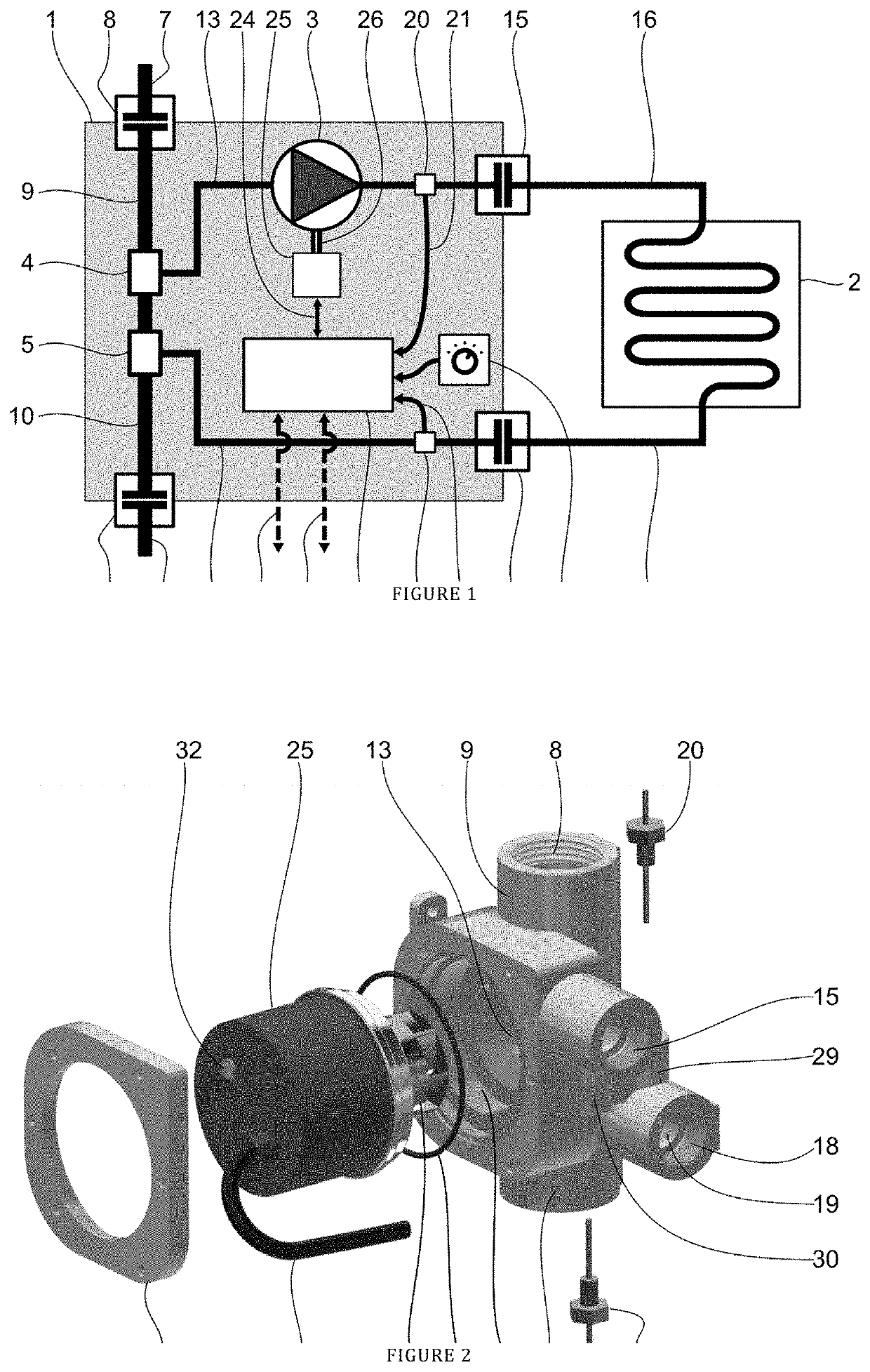
[0021]The connection consists of the device 1 connected through the secondary supply pipe connection 15 and the supply pipe 16 of the heat exchanger 2, and through the return pipe 17 of the heat exchanger 2 and the secondary return pipe connection 18 to the heat exchanger 2. Furthermore, the device 1 is connected through the primary inlet pipe connection 8 to the primary inlet pipe 7, through which the heating medium is supplied from a heat source. From the primary inlet pipe connection 8, the primary inlet 9 is led to the first T-branch 4 connected to the second T-branch 5, from which the primary outlet 10 leads to the primary outlet pipe connection 11 connected to the primary outlet pipe 12, through which the heating medium is returned to the heat source. The secondary supply pipe 12 of the device 1 leads from the first T-branch 4 to the secondary supply pipe connection 15. The secondary return pipe 19 of the device 1 leads from the second T-branch 5 to...


PUM


Abstract

Heat exchanger output control device in a one-pipe heating network characterized in that a first T-branch, which is connected to a second T-branch interconnected to a primary outlet pipe connection of a primary outlet pipe to a heat source through a primary outlet, is connected to the primary inlet pipe connection through a primary inlet. The first T-branch is connected to a secondary supply pipe connection through a secondary supply pipe with a secondary supply temperature sensor, and the second T-branch is connected to a secondary return pipe connection through a secondary return pipe with an additional secondary return temperature sensor. An impeller of a pump is connected to a secondary circuit to pump the heat-transfer medium from the first T-branch through a heat exchanger back to the second T-branch, and to connected to a electrical motor provided with a control unit connected to secondary supply and return temperature sensors.

Description

FIELD OF THE INVENTION[0001]Heat supply control is a basic technological prerequisite for many industrial processes and a required element to control living space comfort. The heat from a heat source is transported via a distribution network to end heat exchangers. Then, the control of heat exchanger power is an important tool to control the temperature in associated processes or rooms.BACKGROUND OF THE INVENTION[0002]Currently, several solutions concerning the heat exchanger control and diagnostics system are known. There is the Czech patent No. 306480 that discloses heat exchanger power control and diagnostics using an electrical pump and several temperature measurements. The flow rate is inferred based on electric power measurements on the pump; the temperature difference on the heat exchanger is measured by the temperature sensors. Using these data and information on a heat-transfer liquid, the heat output of the exchanger is estimated. Then, the output can be controlled to achi...

Claims


Application Information

Patent Timeline
IPC IPC(8): F24D19/10F24D3/02F24D3/10F24D19/00G05D23/19F28F27/00
CPCF24D19/1012F24D3/02F24D3/1058F24D2220/042G05D23/1931F28F27/00F24D2220/0207F24D19/0007F04D29/40F04D29/4273F04D29/4293F04D29/426F24D19/0004Y02B30/70
Inventor BAUMELT, TOMASDOSTAL, JIRIHAUSER, JANKUBES, JIRIVALTR, JIRIZLEVOR, ONDREJ
Owner CZECH TECHNICAL UNIVERSITY IN PRAGUE
Why Eureka
Try Eureka