Valve

a valve and valve body technology, applied in the field of valves, can solve problems such as fault messages in the control system, aggressive components in the medium,

Inactive Publication Date: 2021-03-18
VITESCO TECH GERMANY GMBH
View PDF0 Cites 1 Cited by
  • Summary
  • Abstract
  • Description
  • Claims
  • Application Information

AI Technical Summary

Benefits of technology

The invention is for a valve that is reliable and operates stably over a long period of time. The valve is designed to be simple and low-cost to manufacture. The invention also includes a protective sleeve which separates the piston region from the socket region, preventing aggressive components from reaching the electric contacts. The protective sleeve is made from resistant plastic or high-grade steel, with a thin wall thickness. This design provides effective protection without requiring complex redesigns of valves or requiring significant modification of existing valves.

Problems solved by technology

The disadvantage here is that the medium contains aggressive components that likewise penetrate into the interior of the valve.
In this case, there is the possibility that these components may get into the region of the socket and be deposited on the contacts.
This, in turn, could lead to fault messages in the control system which controls the solenoid.

Method used


Image

  • Valve
  • Valve
  • Valve

Examples


Embodiment Construction

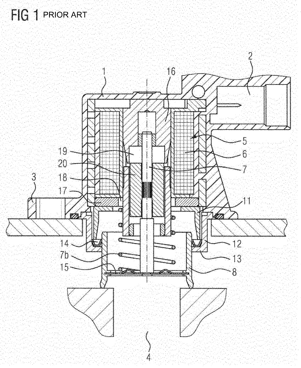
[0016]FIG. 1 shows the valve, which comprises a housing 1. The housing 1 furthermore has an integrally formed flange 3, via which the housing 1 is flanged-mounted on a turbocharger (not illustrated) in the region of a bypass line. The electrical contacting of a solenoid 5, which is arranged in the housing 1, is accomplished via a socket 2. The solenoid 5 has a coil 6, which acts on a metal pin 7. The metal pin 7 is connected to a cup-shaped piston 8, which, at the periphery of its base 9, has a sealing surface 10 that interacts with a valve seat (not illustrated). Here, a spring 7a pushes the piston 8 in the direction of the valve seat. The housing 1 furthermore has a cylindrical section 11 that extends in a direction of the piston 8. A cylinder bushing 12 connected to the housing surrounds the cylindrical section 11. The cylinder bushing 12 has a radially inwardly directed collar 13, on which a seal 14 rests. Here, the seal 14 seals off the piston 8 against the housing 1. Apertures...


PUM


Abstract

A valve has a housing and a solenoid arranged in the housing. The solenoid includes a coil, an armature, an upper stator, and a lower stator, and the stators are designed such that, when a magnetic force acts between the stators, the armature moves axially, further comprising a pin firmly connected to the armature, a cup-shaped piston connected to the pin, a spring, which moves the piston away from the solenoid in the event of a loss of the magnetic force, and a socket arranged on the housing to supply the solenoid with electric energy. A protective sleeve separates the region of the piston from the region of the socket in such a way that no medium from the region of the piston can reach the region of the socket, is arranged in the solenoid.

Description

CROSS REFERENCE TO RELATED APPLICATIONS[0001]This is a U.S. national stage of Application No. PCT / EP2018 / 085247 filed Dec. 17, 2018. Priority is claimed on German Application No. DE 10 2017 223 578.0 filed Dec. 21, 2017 the content of which is incorporated herein by reference.BACKGROUND OF THE INVENTION1. Field of the Invention[0002]The invention relates to a valve comprising a housing and a solenoid arranged in the housing. The solenoid comprises a coil, an armature, an upper stator, and a lower stator. The stators are designed such that, when a magnetic force acts between the stators, the armature moves axially, further comprising a pin, which is firmly connected to the armature, a cup-shaped piston, which is connected to the pin, a spring, which moves the piston away from the solenoid in the event of a loss of the magnetic force, and a socket arranged on the housing to supply the solenoid with electric energy.2. Description of Related Art[0003]Such valves are used, inter alia, as...

Claims


Application Information

Patent Timeline
Patent Type & Authority Applications(United States)
IPC IPC(8): F16K27/02F16K31/06
CPCF16K27/029F16K31/0675F16K31/0655Y02T10/12F02B37/16
Inventor BONANNO, ROSARIO
Owner VITESCO TECH GERMANY GMBH
Why Eureka
Try Eureka