
Integrated imaging-cancer treatment apparatus and method of use thereof

a tumor and imaging technology, applied in the field of tumor imaging and treatment, can solve the problems of reducing the ability to repair damaged dna, affecting the survival rate of patients, and being particularly vulnerable to attack on their dna

Inactive Publication Date: 2021-03-18
BENNETT JAMES P +5
View PDF0 Cites 0 Cited by
  • Summary
  • Abstract
  • Description
  • Claims
  • Application Information

AI Technical Summary

Benefits of technology

The patent describes an integrated system that combines imaging and cancer treatment. The technical effect is that the system can provide a more effective and precise approach to treating cancer by using advanced imaging techniques to better identify and locate the cancerous tissue. This allows for more targeted and effective treatment, reducing the risk of harmful side effects and improving the chances of a complete cure.

Problems solved by technology

These particles damage the DNA of cells, ultimately causing their death.
Cancerous cells, because of their high rate of division and their reduced ability to repair damaged DNA, are particularly vulnerable to attack on their DNA.

Method used


Image

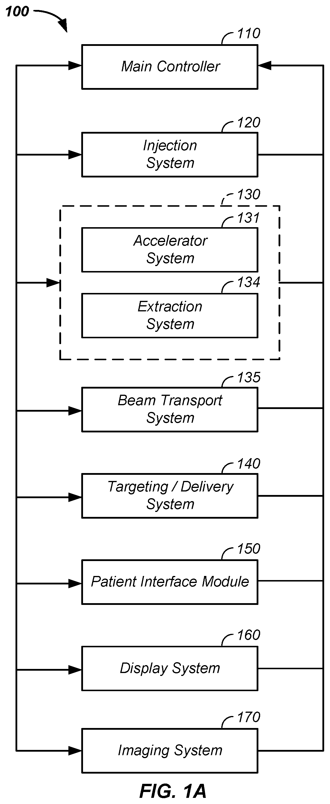
  • Integrated imaging-cancer treatment apparatus and method of use thereof
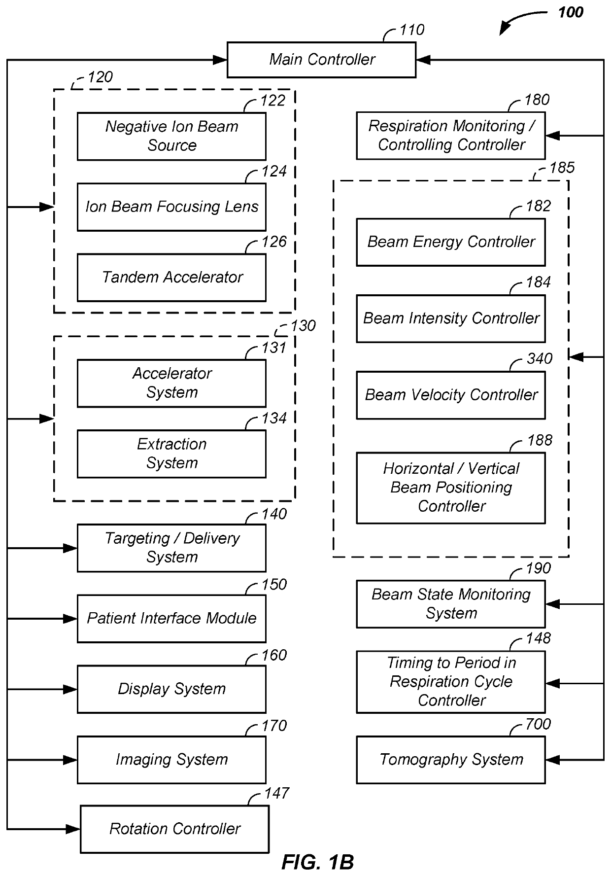
  • Integrated imaging-cancer treatment apparatus and method of use thereof
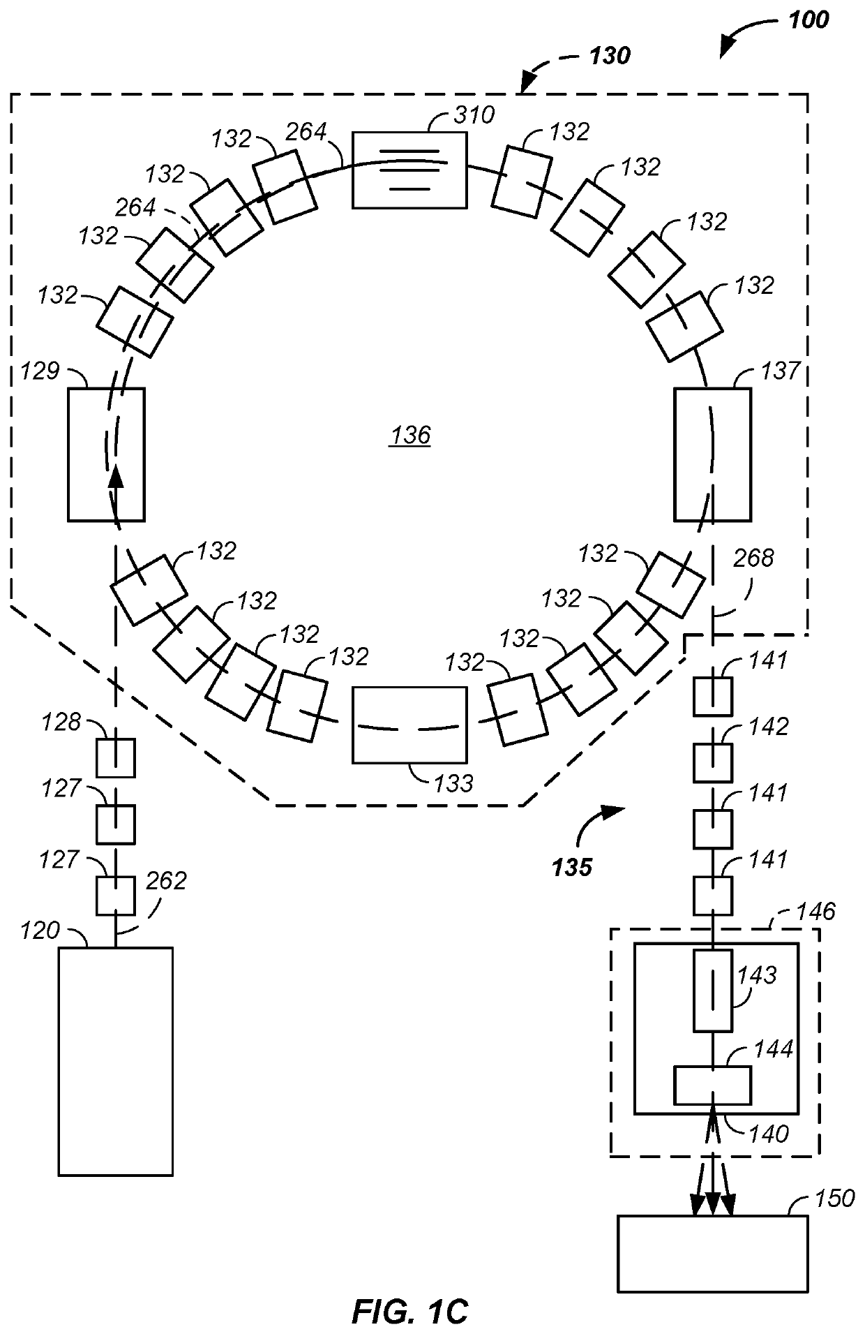
  • Integrated imaging-cancer treatment apparatus and method of use thereof

Examples


example vii

[0119]Still referring to FIG. 2C and FIG. 2D, optionally and preferably geometries of the gating electrode 204 and / or the extraction electrode 206 are used to focus the extracted ions along the initial ion beam path 262.

example viii

[0120]Still referring to FIG. 2C and FIG. 2D, the lower emittance of the electron cyclotron resonance triode extraction system is optionally and preferably coupled with a downbeam or downstream radio-frequency quadrupole, used to focus the beam, and / or a synchrotron, used to accelerate the beam.

example ix

[0121]Still referring to FIG. 2C and FIG. 2D, the lower emittance of the electron cyclotron resonance triode extraction system is maintained through the synchrotron 130 and to the tumor of the patient resulting in a more accurate, precise, smaller, and / or tighter treatment voxel of the charged particle beam or charged particle pulse striking the tumor.

Example X

[0122]Still referring to FIG. 2C and FIG. 2D, the lower emittance of the electron cyclotron resonance triode extraction system reduces total beam spread through the synchrotron 130 and the tumor to one or more imaging elements, such as an optical imaging sheet or scintillation material emitting photons upon passage of the charged particle beam or striking of the charged particle beam, respectively. The lower emittance of the charged particle beam, optionally and preferably maintained through the accelerator system 134 and beam transport system yields a tighter, more accurate, more precise, and / or smaller particle beam or parti...


PUM


Abstract

The invention comprises a method and apparatus for using a single robotic positioning arm to simultaneously move, relative to a proton beam path entering a treatment room containing the patient, both: (1) a patient support and (2) an imaging system. The robotic arm moving the imaging system and patient independently from movement of a nozzle system directing protons into the treatment rooms allows: simultaneously translating past the patient and rotating around the patient an X-ray source of the imaging system; translating a rotatable unit, of the imaging system, longitudinally past the patient on a translation guide rail; moving the patient support and the imaging system through at least four degrees of freedom relative to a movable proton beam; and / or simultaneous or alternating movement of the proton treatment beam and the imaging system relative to the patient.

Description

CROSS-REFERENCES TO RELATED APPLICATIONS[0001]This application is a continuation of U.S. patent application Ser. No. 15 / 603,360 filed May 23, 2017, which is a continuation-in-part of U.S. patent application Ser. No. 15 / 601,982 filed May 22, 2017, which is a continuation-in-part of U.S. patent application Ser. No. 15 / 467,840 filed Mar. 23, 2017, which is a continuation-in-part of U.S. patent application Ser. No. 15 / 402,739 filed Jan. 10, 2017, which is a continuation-in-part of U.S. patent application Ser. No. 15 / 348,625 filed Nov. 10, 2016, which is a continuation-in-part of U.S. patent application Ser. No. 15 / 167,617 filed May 27, 2016, which is a continuation-in-part of U.S. patent application Ser. No. 15 / 152,479 filed May 11, 2016, which is a continuation-in-part of U.S. patent application Ser. No. 14 / 216,788 filed Mar. 17, 2014, which is a continuation-in-part of U.S. patent application Ser. No. 13 / 087,096 filed Apr. 14, 2011, which claims benefit of U.S. provisional patent appl...

Claims


Application Information

Patent Timeline
Patent Type & Authority Applications(United States)
IPC IPC(8): A61N5/10A61B6/00A61B6/03G21K5/04A61B6/04
CPCA61N5/1049G21K1/093A61N5/1039A61B6/037A61B6/547A61N5/1067A61N5/1082A61N5/1077A61B6/032A61N5/1044A61B6/4258G21K5/04A61N5/1037A61B6/0487A61N2005/1061A61N2005/1087A61N2005/1051A61N2005/1097A61N5/107A61B6/4476A61B6/5205A61N5/1069A61N2005/1054A61N2005/1095
Inventor BENNETT, JAMES P.LEE, W. DAVISAMATO, MARK R.RENO, JILLIANRUEBEL, NICKMICHAUD, SUSAN L.
Owner BENNETT JAMES P
Learn More