
Catalytic Reactor Apparatus for Conversion of Plastics

a reactor and catalytic technology, applied in the direction of chemistry apparatus and processes, physical/chemical process catalysts, metal/metal-oxide/metal-hydroxide catalysts, etc., can solve the problems of plastic waste being a huge contributor to environmental pollution, plastics are not biodegradable, and plastic waste is not biodegradabl

Active Publication Date: 2021-03-11
MOLECULE WORKS INC
View PDF0 Cites 6 Cited by
  • Summary
  • Abstract
  • Description
  • Claims
  • Application Information

AI Technical Summary

Benefits of technology

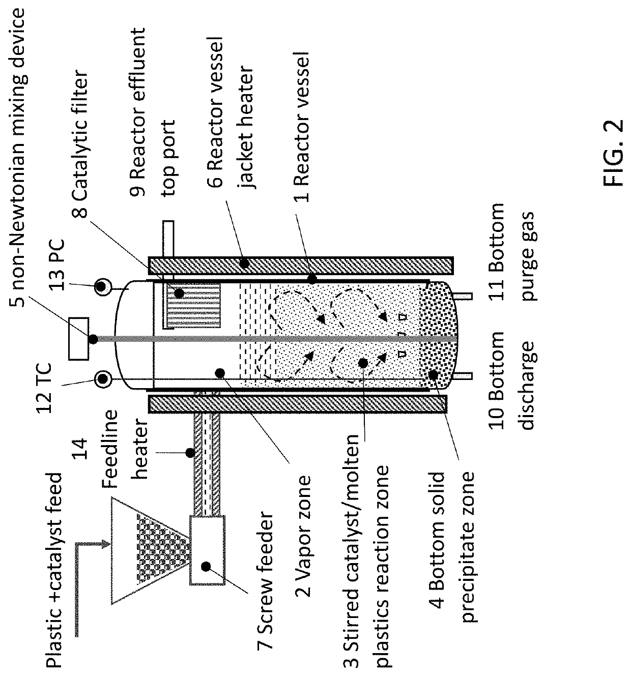
[0008]An integrated reactor apparatus is disclosed for continuous conversion of plastic wastes into useful hydrocarbon products that are preferably in liquid phase at room temperature (<C4). The major components of the reactor apparatus are shown in FIG. 2. The reactor comprises a reactor vessel 1 of aspect ratio (height to diameter) greater than 1. Inside the reactor vessel, there may be three zones: a vapor phase zone 2 in a top portion; a molten plastic+catalyst reaction zone 3 in a middle portion; and a solid precipitation zone 4 in bottom of the reactor vessel 1. Inside the reactor vessel 1, there is also a mixing device 5 generating both radial and axial mixing for achieving uniform catalyst / plastic contacting and effective heat transfer between the vessel wall and interior of the molten plastic+catalyst reaction zone 3. The reactor vessel 1 may be heated on its exterior wall by a heating device 6 (e.g., reactor vessel heater). There may be at least one feed port in upper portion of the reactor vessel 1 for introduction of plastic+catalyst feedstock into the reactor via a feeder device, such as a screw feeder device 7 and feedline heater 14. There may be a catalytic filter 8 connected to the upper portion of the reactor vessel 1 to let hot oil vapor-reactor effluent 9 escape or vent out of the reactor vessel 1 while retaining of fine particulates (catalysts, chars, etc.) and / or plastic fragments (macro-molecules) inside the reactor vessel 1. On bottom of the reactor vessel 1, there may be a bottom portion discharge port 10 for discharge of the solid residuals out of the reactor vessel 1 and another purge gas port 11 for introduction of purge gas into the reactor vessel 1. There may be at least one top portion thermal couple (TC) port 12 to measure temperature profiles inside the reactor vessel 1 and at least one top portion pressure gauge (PC) port 13. The plastic and catalyst feed may be preheated via a feedline heater 14 prior to entering the reactor vessel 1.
[0009]The plastic waste may be continuously converted into the hydrocarbon product on the reactor apparatus by i) pushing the plastic+catalyst feed into the reactor vessel 1 by use of a feeder device, such as a screw feeder 7, ii) letting the plastic feed melt and crack into smaller molecules through continuous mixing and contacting with the catalyst in the molten plastic+catalyst reaction zone 3 that may be heated over a temperature range of 300 to 600° C. under nearly atmospheric pressure, iii) withdrawing hot (>200° C.) oil vapor from top portion of the reactor vessel 1 and filtering out particulates and / or macromolecules, and iv) condensing the filtered oil vapor into liquids at environmental temperatures.

Problems solved by technology

Plastics are not biodegradable.
It takes many years for plastic materials to decompose.
As a consequence, plastic waste is a huge contributory to environmental pollution.
Incineration of solid wastes, such as plastics, tends to generate toxic air emissions.
As a result, incineration is not a viable solution to the problem of plastic waste.
Incineration, gasification, or cracking of PVC may result in potent air pollutants such as hydrocarbon chloride and corrosive hydrogen chloride gas.
Highly toxic C—N molecules may be produced from cracking reactions, such as hydrogen cyanide.
However, the thermal process is typically associated with high reaction temperatures and high levels of production of side products (fuel gas, char).

Method used


Image

  • Catalytic Reactor Apparatus for Conversion of Plastics
  • Catalytic Reactor Apparatus for Conversion of Plastics
  • Catalytic Reactor Apparatus for Conversion of Plastics

Examples


example i

al Effects of Catalyst on Plastic Decomposition

[0077]Effects of catalyst addition on decomposition activity of the plastic were surveyed on thermogravimetric analyzer (TGA) by heating in nitrogen gas at 2° C. / min. The trash bag made of low-density-polyethylene (LDPE) was cut into fragments of a few mm sizes and blended with dry ZSM-5 zeolite powder. FIG. 11 shows weight change profiles of bare LDPE and LDPE added with two different amounts of the catalyst. There was little weight change for the bare LDPE at temperatures below 350° C. When the temperature reached about 380° C., LDPE weight rapidly decreased. Most plastics decomposed within 40 min between 380 and 470° C. Addition of 3 wt. % catalyst (Cat 1) into the LDPE fragments did not make any difference. Because the LDPE fragment was very fluffy, it was not possible to obtain uniform mixing of the LPDE and catalyst powder at this loading level in physical mixing method. The catalyst powder was segregated from the plastic fragment...

example ii

ests of PE Reactivity in Tubular Reactor

[0080]Since small amounts of the material (˜10 mg) were loaded on the sample pan in TGA tests, the material was nearly isothermal and had the temperature same or close to the sample pan temperature measured. In actual reactor operation, there could be significant temperature difference between the reactor temperature and actual material temperature. The reactivity of bare PE was tested in quartz tube reactor with the same LDPE and HDPE materials as used in Example I. The LDPE and HDPE were loaded in the respective ceramic boats, and the boats were placed inside a quartz tube reactor tube. Continuous nitrogen gas flow was used to purge inside the reactor tube while the outside of the reactor tube was heated by a furnace at 2° C. / min to 450° C. with 60 min-hold at 450° C. It was observed that complete melting of LDPE and HDPE occurred at about 370° C. and 420° C., respectively. As listed in Table 1, the theoretical melting points for LDPE and HD...

example iii

E Conversion in the Tubular Reactor

[0081]Catalytic decomposition was tested in the same tubular reactor under the same conditions as example II. The LDPE and HDPE chips were physically mixed with about 5 wt. % zeolite catalyst powder, respectively. The catalyst-added LDPE and HDPE were placed in respective ceramic boats, and the boats were loaded in the tubular reactor. Some amounts of oil vapor were observed and collected at the reactor outlet during 450° C.-hold. After the heating was done and the reactor was opened, significant amounts of wax were found deposited on the reactor tube wall in the purge gas exit region. FIG. 14a shows the wax deposit collected. All the plastic materials in the two boats were gone (FIG. 14b). There was only catalyst powder in the ceramic boat. The catalyst in the HDPE boat looked grey, while the catalyst in the LDPE boat looks black. The dark color indicates coking on the catalyst. The plastics in both boats were cracked into wax molecules that left ...


PUM

PropertyMeasurementUnit
channel widthsaaaaaaaaaa
particle sizeaaaaaaaaaa

Abstract

A catalytic reactor apparatus is disclosed for continuous conversion of plastic wastes into liquid fuels by dispersing a cracking catalyst in molten plastics and cracking plastic macromolecules into smaller hydrocarbons within boiling point range of gasoline and diesel fuel at temperatures significantly lower than thermal pyrolysis and thermal cracking. The catalyst/plastic mixing and heat transfer from the reactor wall to the reaction zone are enhanced using non-Newtonian stirrer. A catalytic membrane filter is used to keep the catalyst fines and unconverted plastic particulates inside the reactor while letting the desirable hydrocarbon vapor be withdrawn out of the reactor.

Description

RELATED APPLICATIONS[0001]This application claims priority to U.S. Provisional Application No. 62 / 896,200 entitled “Catalytic Reactor Apparatus for Conversion of Plastics”, filed Sep. 5, 2019, the entire contents of which are hereby incorporated by reference for all purposes.FIELD OF INVENTION[0002]The present invention relates to reaction apparatus and process for conversion of plastic wastes into liquid fuels.BACKGROUND OF INVENTION[0003]The world produces about three hundred million tons of plastics each year. Plastic wastes has become a great concern to the environment and human society. The global recycling rate of plastics is only 6% to 9% of plastic consumption. Currently, landfill is the most common disposal method in the world for plastics. Plastics are not biodegradable. It takes many years for plastic materials to decompose. As a consequence, plastic waste is a huge contributory to environmental pollution. Incineration of solid wastes, such as plastics, tends to generate ...

Claims


Application Information

Patent Timeline
Patent Type & Authority Applications(United States)
IPC IPC(8): C10G1/10B01J29/40B01J35/02
CPCC10G1/10B01J29/40C10G2300/4012C10G2300/1003B01J35/026B01J35/065B01J23/755
Inventor LIU, WEIXU, BANG-CHENG
Owner MOLECULE WORKS INC
Learn More