Water ionizer including stacked electrolyzer and flow switching device, with inlet being separate from outlet

a technology of flow switching device and water ionizer, which is applied in the direction of filtration separation, separation process, chemistry apparatus and processes, etc., can solve the problems of reducing the reliability of the product to consumers, complicated fabrication process, and disadvantageous reduction of electrolysis efficiency, so as to improve the efficiency of electrolysis and prevent the scale in the anode chamber. , the effect of simplifying the assembly process

Active Publication Date: 2021-03-04
ALKAMEDI CO LTD
View PDF0 Cites 0 Cited by
  • Summary
  • Abstract
  • Description
  • Claims
  • Application Information

AI Technical Summary

Benefits of technology

[0032]According to the present invention, which water entering an input regulator is distributed at a predetermined ratio before being supplied to an electrolyzer module, such that an unnecessary amount of acidic water to be discarded is minimized, so that the water ionizer can be used being environmentally friendly.
[0033]In addition, water supplied from the input regulator is directed to pass through the electrolyzer module in a crossing manner to delay flows of water, thereby improving the efficiency of electrolysis.
[0034]In addition, polarities of voltages applied to electrode plates are changed so that anode chambers and cathode changers repeatedly alternate with each other, thereby preventing scale in the anode chambers.
[0035]In additio...

Problems solved by technology

This may disadvantageously lower the reliability of the product to consumers.
In addition, since tap water supplied to the electrolzyer is divided into alkaline water and acidic water by electrolysis and then is directly discharged through a flow switching valve, the efficiency of electrolys...

Method used


Image

  • Water ionizer including stacked electrolyzer and flow switching device, with inlet being separate from outlet
  • Water ionizer including stacked electrolyzer and flow switching device, with inlet being separate from outlet
  • Water ionizer including stacked electrolyzer and flow switching device, with inlet being separate from outlet

Examples


Embodiment Construction

[0050]Hereinafter, a water ionizer including a stacked electrolyzer and a flow switching device, with an inlet being separate from an outlet, according to exemplary embodiments of the present invention will be described in detail with reference to the accompanying drawings. In the following description of the present invention, a detailed description of known functions and configurations incorporated herein will be omitted in the situation in which the subject matter of the present invention may be rendered rather unclear thereby. The terms to be used hereinafter are defined in consideration of functions thereof in embodiments of the present invention, but may vary depending on the intentions of users or operators, as well as practices. Therefore, the terms shall be defined on the basis of the description throughout the specification.

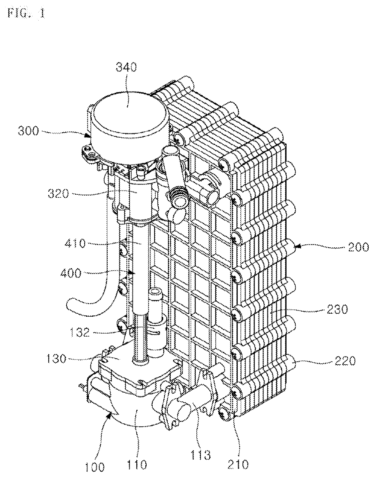
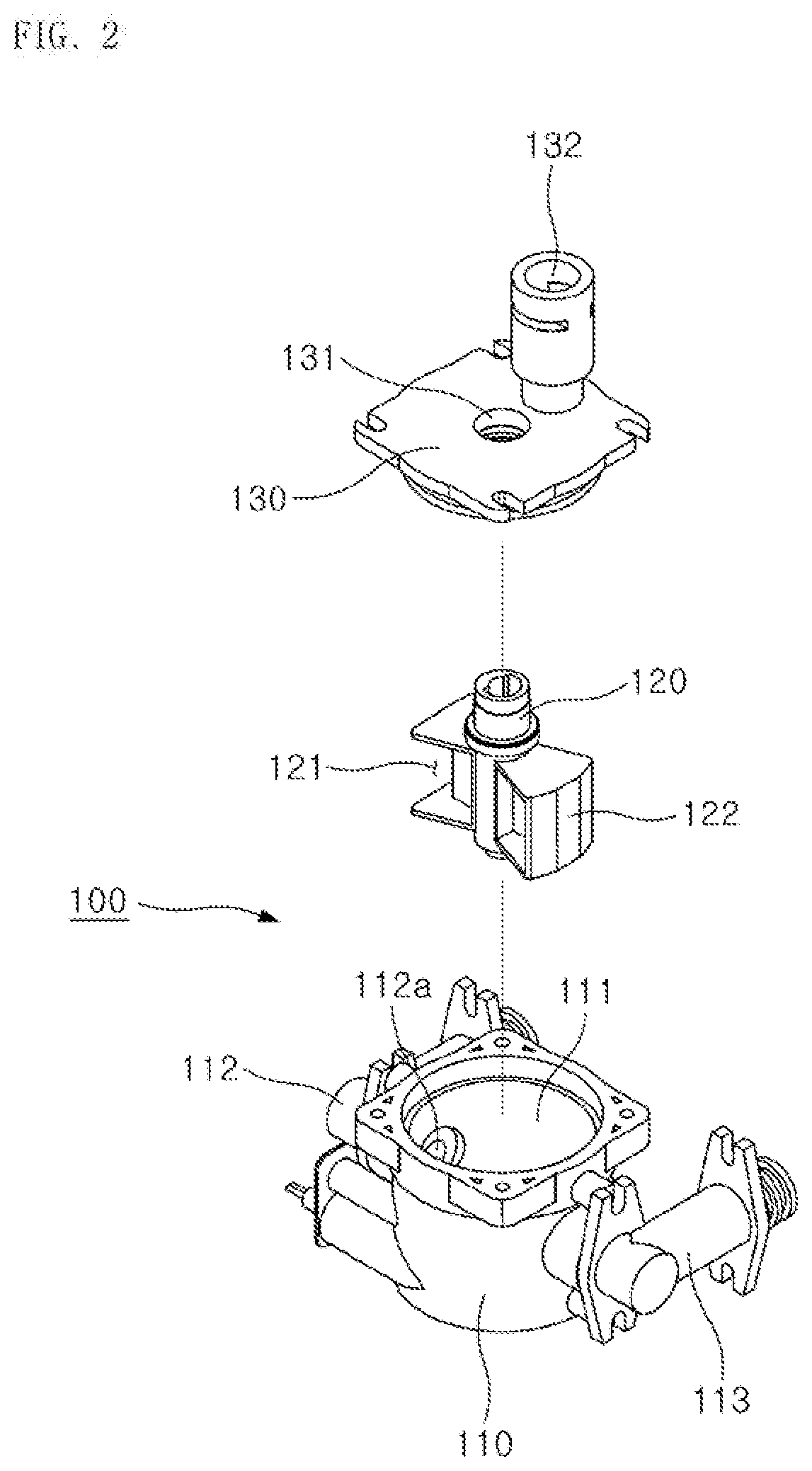
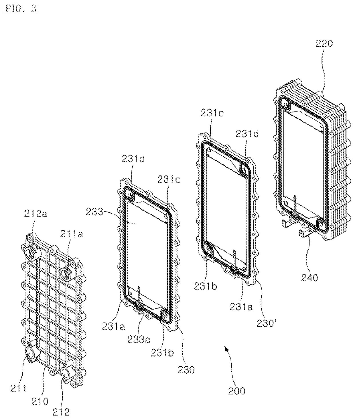
[0051]First, as illustrated in FIGS. 2 to 7, the water ionizer according to the present invention includes an input regulator 100, an electrolyzer modu...


PUM

PropertyMeasurementUnit
Ratioaaaaaaaaaa
Electric potential / voltageaaaaaaaaaa
Efficiencyaaaaaaaaaa

Abstract

A water ionizer includes a stacked electrolyzer and a flow switching device, with an inlet being separate from an outlet. Water entering an input regulator is distributed at a predetermined ratio before being supplied to an electrolyzer module to minimize acidic water to be discarded. Water supplied from the input regulator is directed to pass through the electrolyzer module in a crossing manner to delay flows of water to improve the efficiency of electrolysis. Electrolyzer cells are stacked on and fitted to each other to simplify an assembly process and improve convenience. Electrode plates of the electrolyzer module are fixedly fitted into a frame to facilitate an assembly process and improve a fabrication process. The input regulator and a flow switching output unit are connected via a connecting shaft to synchronize the operations thereof to obtain reliability.

Description

CROSS REFERENCE TO RELATED APPLICATION[0001]This application claims the benefit under 35 U.S.C. Section 371, of PCT International Application No. PCT / KR2019 / 015293, Nov. 12, 2019 filed, which claimed priority to Korean Patent Application No. KR 10-2018-0147944, filed Nov. 27, 2018, the disclosures of which are hereby incorporated by the references.BACKGROUND OF THE INVENTIONField of the Invention[0002]The present invention relates generally to a water ionizer and, more particularly, to a water ionizer including a stacked electrolyzer and a flow switching device, with an inlet being separate from an outlet, in which water entering an input regulator is distributed at a predetermined ratio before being supplied to an electrolyzer module so as to minimize an unnecessary amount of acidic water to be discarded, water supplied from the input regulator is directed to pass through the electrolyzer module in a crossing manner to delay flows of water so as to improve the efficiency of electro...

Claims


Application Information

Patent Timeline
IPC IPC(8): C02F1/461
CPCC02F1/4618C02F2201/005C02F2201/46165C02F2201/46115C02F2201/4611C02F2201/004C02F2201/007C02F1/006C02F2201/4613C02F2201/46145C02F2201/4617C02F2201/46185B01D35/06
Inventor KIM, KI HWANKIM, JONG SEOB
Owner ALKAMEDI CO LTD
Why Eureka
Try Eureka