
Buffer gear set for power tool

Inactive Publication Date: 2021-02-04
TRANMAX MACHINERY
View PDF0 Cites 1 Cited by
  • Summary
  • Abstract
  • Description
  • Claims
  • Application Information

AI Technical Summary

Benefits of technology

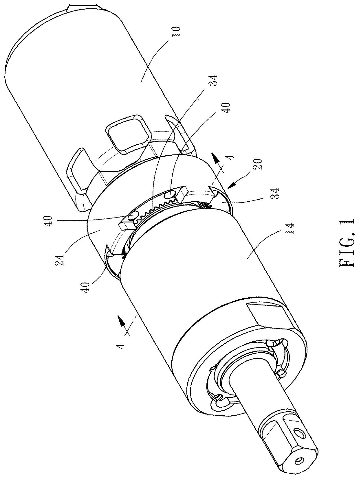
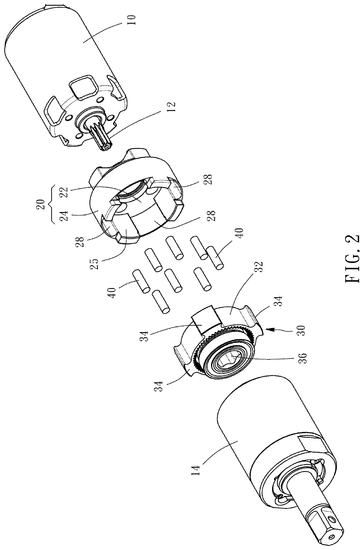
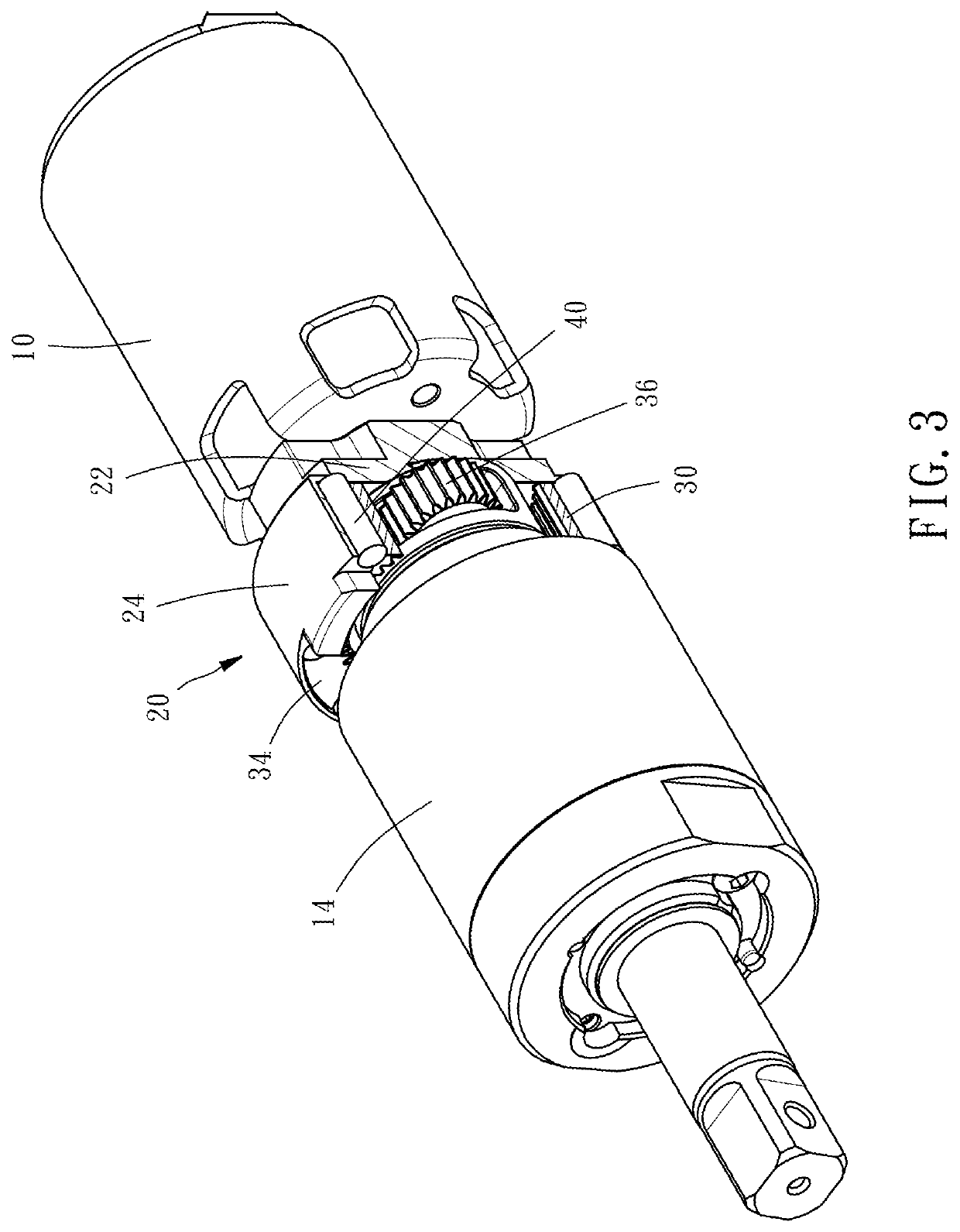
The present invention is a buffer gear set for power tools that reduces the impact and noise of the tool, improving work efficiency and quality. It consists of an outer ring seat and an inner ring seat with a planetary gear set in between. A space is created between the two seats that contains a buffer member that absorbs external force, reducing the impact of the tool. This buffer gear set acts as a shock absorber and improves the overall performance of power tools.

Problems solved by technology

However, a power tool will continue to produce a reaction force to the user during operation, often accompanied by noise or vibration to make the user feel uncomfortable.
Long-term work can easily affect work efficiency and work quality.

Method used


Image

  • Buffer gear set for power tool
  • Buffer gear set for power tool
  • Buffer gear set for power tool

Examples


Embodiment Construction

[0013]The technical content and features of the present invention will be described in detail below by referring to the preferred embodiment and the annexed drawings. The invention can be widely applied to various forms or specifications of power tools Those skilled in the art can understand that the description of the present preferred embodiment belongs to the generic description of the application field. For example, a material or shape term includes and is not limited to the material or shape specified by the description, and the positional terms include and are not limited to setting, approaching, connecting, or abutting. The number of elements “one” includes one and more than one number of complex components. The directional expressions such as “upper”, “lower”, “inside”, “outside”, “top” and “bottom” mentioned in the contents of this specification are merely illustrative terms used in the normal direction of use, not intended to limit the scope of the claim.

[0014]Referring to...


PUM


Abstract

A buffer gear set mounted between a motor and a transmission assembly of a power tool is disclosed to include an outer ring seat and an inner ring seat coaxially arranged together, a planetary gear set mounted in the outer ring seat, accommodation spaces defined between the outer ring seat and the inner ring seat, and buffer members respectively accommodated in the accommodation spaces. When an external force is applied between the outer ring seat and the inner ring seat, the buffer members absorb a part of the external force transmitted between the outer ring seat and the inner ring seat, thereby reducing the impact of the overall power tool, achieving shock absorption, reducing noise and improving work efficiency and quality.

Description

BACKGROUND OF THE INVENTION1. Field of the Invention[0001]The present invention relates to power tool technology, and more particularly to a buffer gear set for power tool.2. Description of the Related Art[0002]Power tools are configured for a variety of tightening or loosening operations using a rotating shaft. In addition to being generally a simple screwdriver, some power tools can also generate impact force to increase the rotational torque, so as to enhance the effect of tightening and disassembling components.[0003]However, a power tool will continue to produce a reaction force to the user during operation, often accompanied by noise or vibration to make the user feel uncomfortable. Long-term work can easily affect work efficiency and work quality.SUMMARY OF THE INVENTION[0004]The present invention has been accomplished under the circumstances in view. It is the main object of the present invention to provide a buffer gear set for power tool, which can reduce the impact of the...

Claims


Application Information

Patent Timeline
IPC IPC(8): F16H35/10F16H3/44B25B21/00
CPCF16H35/10F16H2200/20B25B21/00F16H3/44B25F5/001B25F5/006F16H57/028B25B21/02F16H57/0006F16H57/08
Inventor CHEN, HSIN-CHI
Owner TRANMAX MACHINERY
Learn More