Wind energy park with airborne wind energy systems and a direct current (DC) internal grid

Active Publication Date: 2021-02-04
VESTAS WIND SYST AS
View PDF0 Cites 7 Cited by
  • Summary
  • Abstract
  • Description
  • Claims
  • Application Information

AI Technical Summary

Benefits of technology

The invention is about a wind energy park with multiple AWES that can stabilize power production. Connecting the AWES through an electrical DC network can reduce the size of the grid converter and make the system more stable. The DC network also allows for more efficient energy storage. Additionally, the patent describes how the AWES can be adjusted to increase power production, such as by changing the pitch angle or speed of the kite or moving them to areas with more pull or extraction force. The invention also suggests ways to reduce power production by actively extending or reducing the cable length of certain AWES. Overall, the invention enhances the efficiency and stability of wind energy parks.

Problems solved by technology

Such large scale use of AWES may represent a technical challenge due to differences as compared with other renewable energy sources, e.g. solar PV and conventional wind turbines.
In particularly, the integration of these large wind energy parks with a plurality of AWES with the electrical grid may represent a problem with the typically many requirements and detailed constraints for producing electrical energy to the electrical grid in most countries and areas, these grid requirements normally being regulated by the transmission system operators (TSO).

Method used


Image

  • Wind energy park with airborne wind energy systems and a direct current (DC) internal grid
  • Wind energy park with airborne wind energy systems and a direct current (DC) internal grid
  • Wind energy park with airborne wind energy systems and a direct current (DC) internal grid

Examples


Embodiment Construction

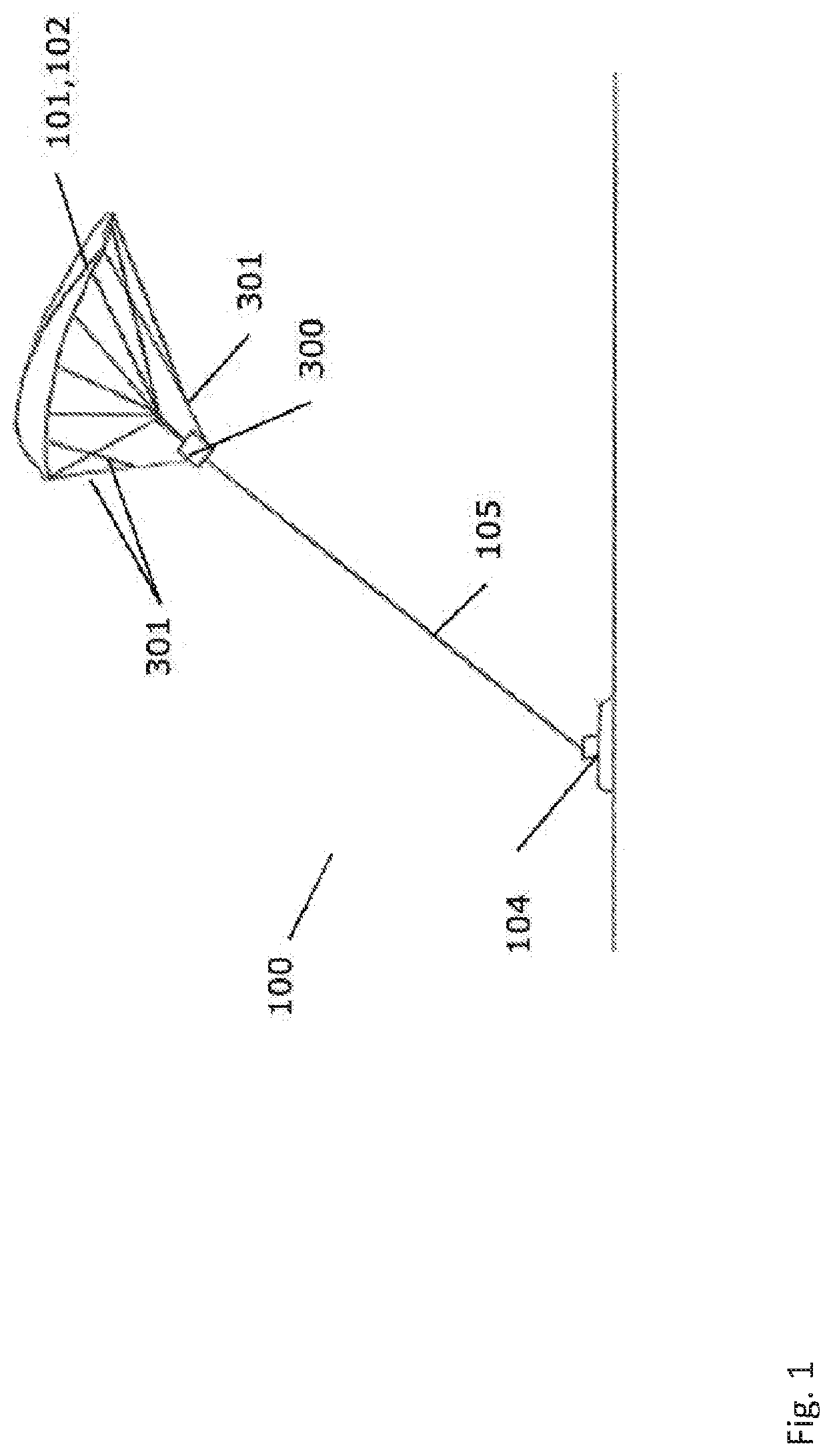
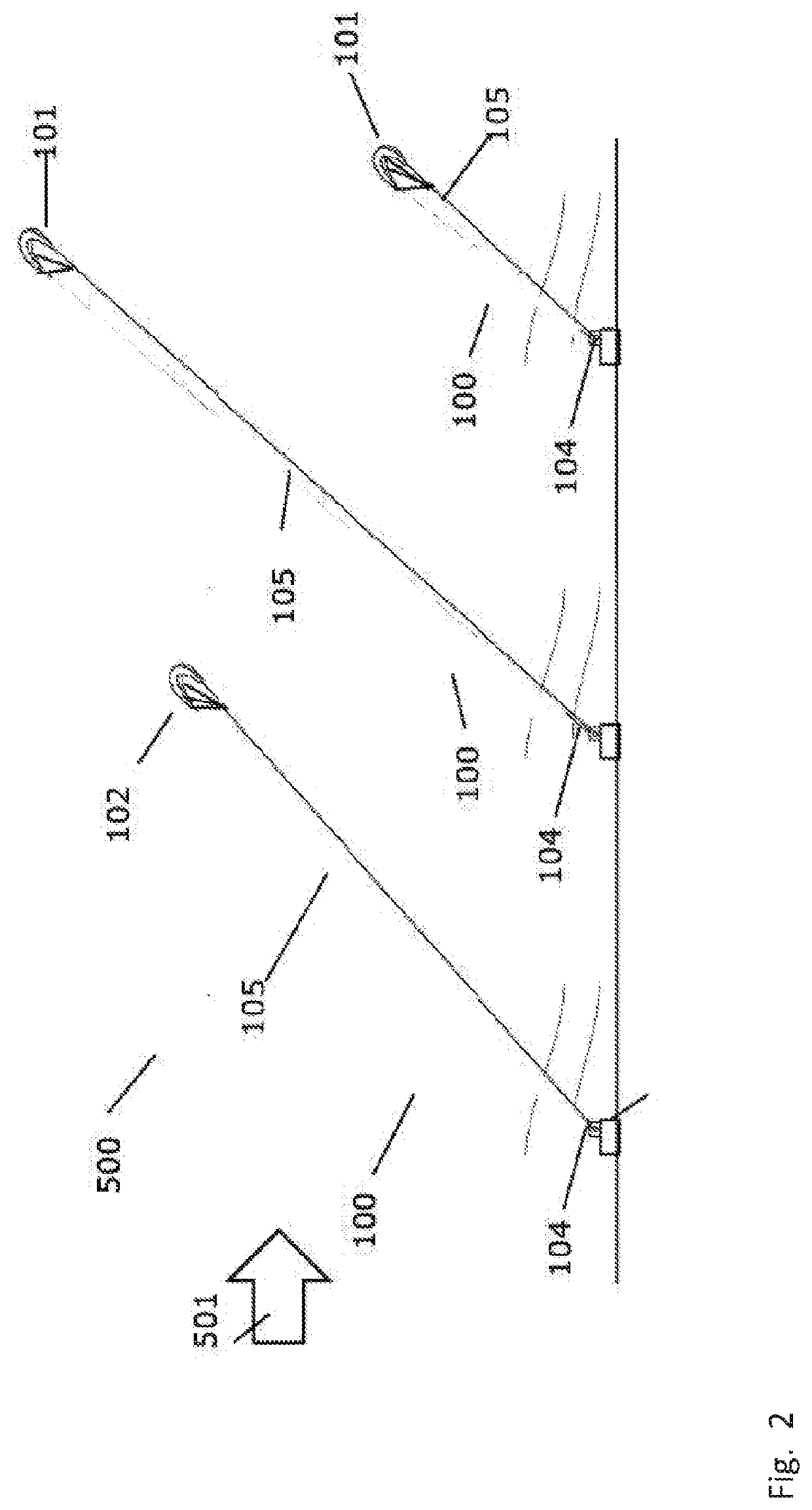
[0089]FIG. 1 is a perspective view of an airborne wind energy system 100 for use in a wind energy park an according to embodiments of the invention. The airborne wind energy systems 100 comprises a wind engaging member 101 catching and moved by the wind and connected to a ground station 104 via one or more cables 105. The wind engaging member 101 is in the form of a kite connected to a control unit 300 via steering lines 301 and to a winch system (not shown) in the ground station 104 typically via a single cable 105. The operation of the kite 101 can be fully or partly controlled by the operation of the steering lines 301 by the control unit and in addition to the extraction and retraction of the cable 105 controlled from the winch system.

[0090]The extraction of the cable 105 from the winch system generates mechanical energy which is transferred via the winch system to a generator positioned on the ground station 104. The generator is in turn electrically coupled to a power transmis...


PUM


Abstract

The present invention relates to wind energy park connected to an electrical grid, having airborne wind energy systems (AWES), e.g. with kites. The wind energy park has an electrical DC network connecting the plurality of AWES and a grid converter unit for converting DC to AC, and transmit AC to the electrical grid. The wind energy park control unit controls the AWES to produce electrical power to the electrical grid by alternating between a power production phase, and a recovery phase so to balance the supply of power to the electrical grid according a demanded setpoint. An advantage is that the grid converter may be smaller, as compared to an AC network, because the power is evened out with the negative power from the AWES being in recovery phase. In this way, the invention stabilizes the grid and has a grid forming capability.

Description

FIELD OF THE INVENTION[0001]The present invention relates to a wind energy park with a direct current (DC) internal grid, the wind energy park comprising a plurality of airborne wind energy systems (AWES). The invention also relates to a corresponding method for controlling a wind energy park, a corresponding control unit for a wind energy park, and a computer program product enabling a computer system to carry out the operations of the method.BACKGROUND OF THE INVENTION[0002]Recently, a new class of wind energy converters has received a considerable interest known commonly as ‘airborne wind energy systems’ (AWES), which are capable of capturing the wind energy in atmospheric layers not reachable by traditional wind turbines mounted on the ground.[0003]Various airborne wind energy systems, being capable of capturing wind energy at a higher altitude than traditional wind turbines, are known. Common to these systems is that a part of the system is launched to a high altitude, where th...

Claims


Application Information

Patent Timeline
IPC IPC(8): F03D9/25F03D7/00F03D5/00B64C39/02B64C31/06H02J3/16H02J3/32H02J3/38
CPCF03D9/257F03D7/00F03D5/00B64C39/022B64C31/06H02J2310/44H02J3/32H02J3/381H02J2300/28H02J2300/24H02J2300/40H02J3/16H02S10/12H02J2300/20Y02E10/56Y02E10/76H02J3/28H02J3/48H02J3/50B64U10/60
Inventor LINDHOLM, MORTENNIELSEN, THOMAS S. BJERTRUPPETERSEN, TORBENHELLE, LARS
Owner VESTAS WIND SYST AS
Why Eureka
Try Eureka