
Collet Chamber for Weapons

a technology of collet chamber and weapon, which is applied in the field of weapons, can solve the problems of reducing the extraction force, affecting the extraction effect, and only extending the flute from the cartridge mouth to the part, so as to reduce the extraction force

Active Publication Date: 2019-01-17
ARMY US SEC THE
View PDF5 Cites 3 Cited by
  • Summary
  • Abstract
  • Description
  • Claims
  • Application Information

AI Technical Summary

Benefits of technology

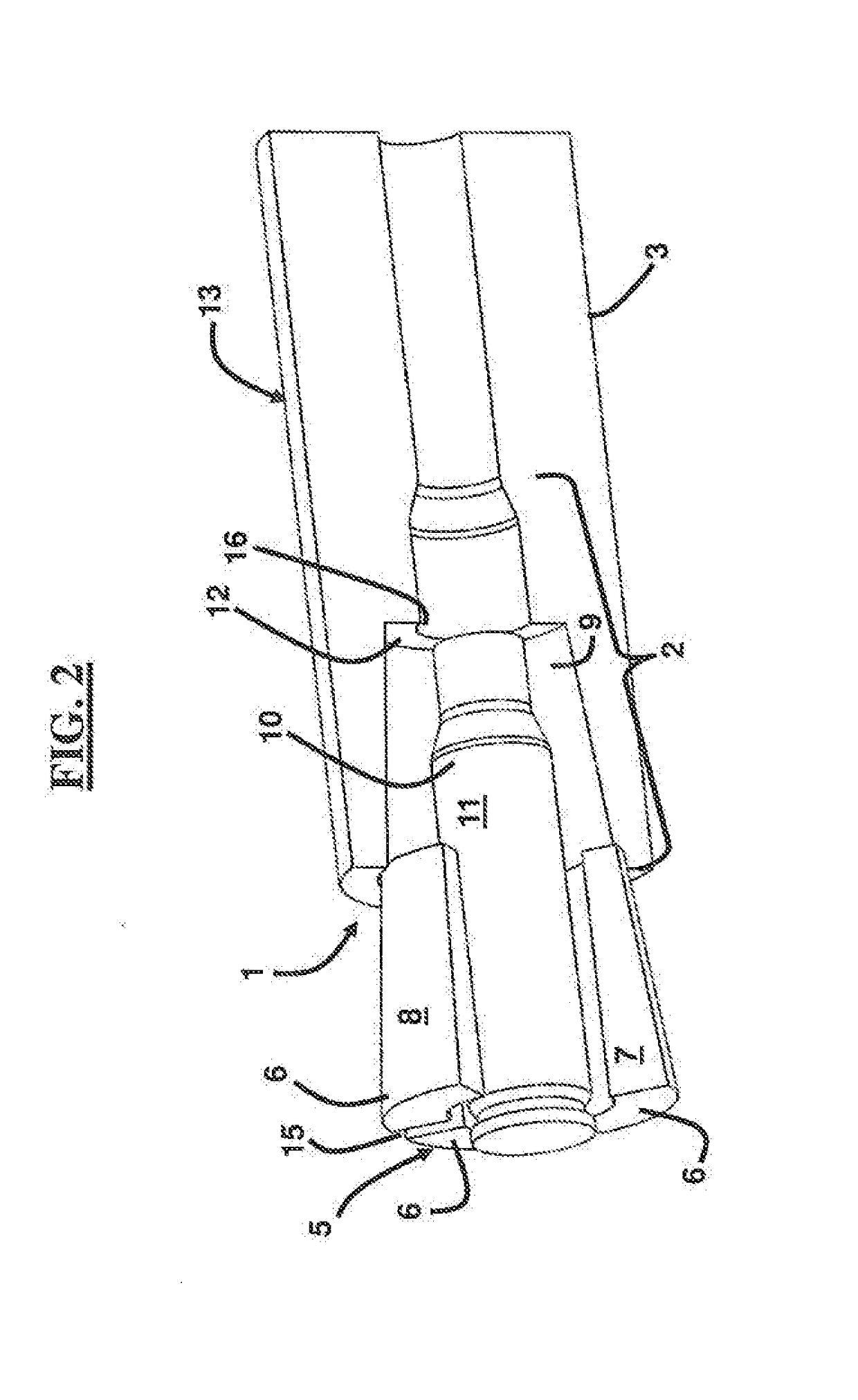
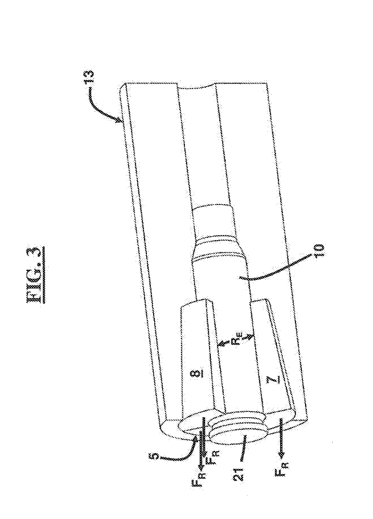
The patent describes a system that reduces the force required to remove a spent shooting cartridge case from a weapon after firing. The system includes a chamber and movable components that expand radially when the cartridge case expands, creating a force that pushes the cartridge case backward. The chamber may have a tapered wall, and the movable components may align with the wall. Each movable component has a tapered outer surface with an angle greater than the angle of the cartridge case. The system may include a back wall that abuts the movable components. The movable components may contract radially. The technical effect of this system is to make it easier and safer to remove a spent shot cartridge case from a weapon after firing.

Problems solved by technology

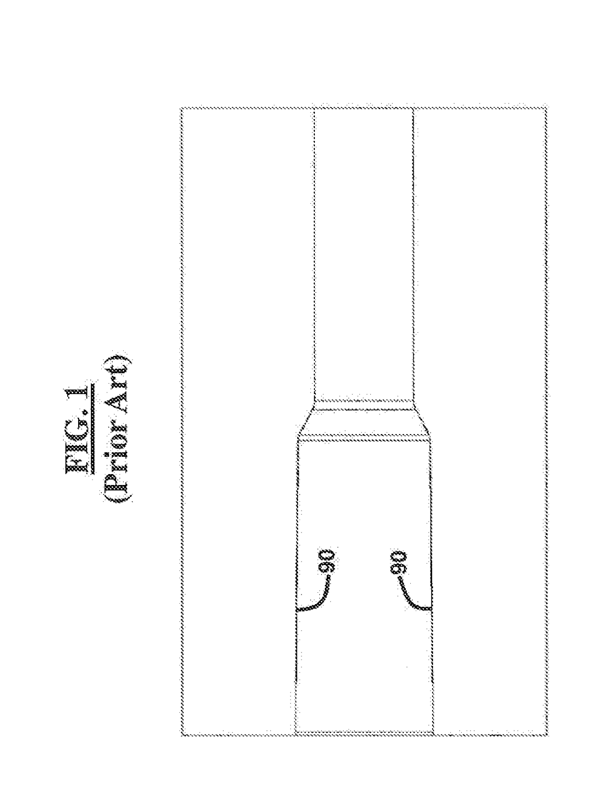
Fluted chambers deposit a tremendous amount of soot due to the combustion gasses on internal surfaces of the weapon and the spent cartridge case, which can lead to weapon malfunctions and stoppages as the soot builds up in the weapon.
Another downside of the fluted chamber is that the flutes can only extend from the cartridge mouth to part-way down the chamber.
Especially in higher pressure cartridges, swelling in the base of the cartridge provides a substantial preload on the chamber and thus, much greater extraction forces are required.
These lubricants reduce the friction coefficients between the ammunition and chamber walls, thus, lowering the extraction force.
These coatings have a limited lifetime due to the pressures and wear on the systems.
The coatings tend to be cost prohibitive when used on ammunition and may present a danger to the gun / operator if used improperly.

Method used


Image

  • Collet Chamber for Weapons
  • Collet Chamber for Weapons
  • Collet Chamber for Weapons

Examples


Embodiment Construction

[0025]The embodiments herein and the various features and advantageous details thereof are explained more fully with reference to the non-limiting embodiments that are illustrated in the accompanying drawings and detailed in the following description. Descriptions of well-known components and processing techniques are omitted so as to not unnecessarily obscure the embodiments herein. The examples used herein are intended merely to facilitate an understanding of ways in which the embodiments herein may be practiced and to further enable those of skill in the art to practice the embodiments herein. Accordingly, the examples should not be construed as limiting the scope of the embodiments herein.

[0026]The embodiments herein provide a chamber assembly and system containing an insert with movable components referred to herein as a collet chamber. Referring now to the drawings, and more particularly to FIGS. 2 through 8B, where similar reference characters denote corresponding features co...


PUM


Abstract

A system for reducing an extraction force required for removing a spent munition cartridge case from a weapon after firing, the system including a chamber; and a plurality of movable components in the chamber that are configured to radially expand with a corresponding expansion of a fired munition cartridge case, wherein radial expansion of the plurality of movable components causes a rearward force on the plurality of movable components and the spent munition cartridge case. The chamber may include a tapered wall, and the plurality of movable components may matingly align with the tapered wall. The plurality of movable components may align with one another. Each movable component may include a tapered outer surface comprising an angle greater than an angle of an outer surface of a pre-fired cartridge case.

Description

GOVERNMENT INTEREST[0001]The embodiments herein may be manufactured, used, and / or licensed by or for the United States Government without the payment of royalties thereon.BACKGROUNDTechnical Field[0002]The embodiments herein generally relate to weapons, and more particularly to techniques for improving extraction of spent munition cartridge casings from a weapon after firing.Description of the Related Art[0003]Cartridge case pressures are being increased in ammunition to provide better performance. A commonly used method to help with cartridge case extraction is the use of a fluted chamber, which is actively used in several platforms including rifles. Fluting a chamber includes creating channels on the surface of the chamber that allow for combustion gasses to flow around the outside of the cartridge case. Combustion gases equalize the pressure difference across the cartridge case, reducing the permanent radial expansion that causes difficult cartridge case extraction. Fluted chambe...

Claims


Application Information

Patent Timeline
Patent Type & Authority Applications(United States)
IPC IPC(8): F41A15/14F41A21/12
CPCF41A21/12F41A15/14
Inventor MICHLIN, ALEX
Owner ARMY US SEC THE
Learn More