
Tool for Removing a Cap From a Medical Injection Device

a technology for injection devices and tools, which is applied in the direction of intravenous devices, infusion needles, other medical devices, etc., can solve the problems of preventing the access of the safety device, the user may not grip the cap properly, and the inconvenient use of the medical injection device by a patient or medical staff, so as to prevent any coring of the inner shield. , the effect of convenient us

Pending Publication Date: 2021-02-04
BECTON DICKINSON FRANCE
View PDF6 Cites 2 Cited by
  • Summary
  • Abstract
  • Description
  • Claims
  • Application Information

AI Technical Summary

Benefits of technology

The technical effects of this patent are to provide a tool for easily removing a cap without damaging the inner shield of a medical injection device. The tool is designed to not exert any axial force on the cap and to have a sufficient gripping section to facilitate the removal of the cap. Additionally, the tool has a gripping zone on the outer surface for better handling by the user, especially when pulling the tool in the distal direction.

Problems solved by technology

However, if the pull-out force is too high, the medical injection device is not convenient for use by a patient or medical staff.
Indeed, since the outer surface of the cap is substantially smooth and / or since the cap is substantially small, the user may not grip it properly.
In particular, when the medical injection device is provided with a safety device, which is intended to protect the needle tip after the injection, the safety device itself may hinder access to the cap.
However, such cap removers may not be fully satisfactory.
Depending on its intensity, such an effort may cause the medical injection device to be withdrawn from the safety device, cause the needle to pierce the soft material if any and bring back small residues of the soft material (said effect is called coring), and / or deform the needle.
This may also result in a loss of tightness between the cap and the medical injection device.

Method used


Image

  • Tool for Removing a Cap From a Medical Injection Device
  • Tool for Removing a Cap From a Medical Injection Device
  • Tool for Removing a Cap From a Medical Injection Device

Examples


Embodiment Construction

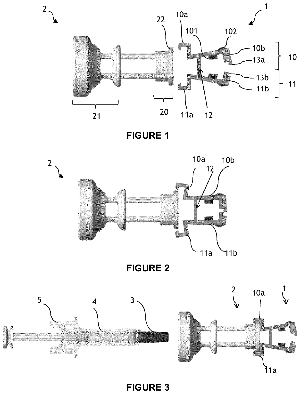
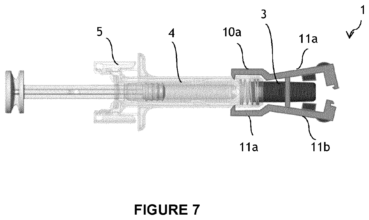
[0044]The cap removal tool comprises a pair of opposite jaws that are connected by an elastic interface about which they are pivotable.

[0045]Each jaw comprises a distal portion configured to surround at least a part of the cap, and a proximal portion configured to cooperate with a part of the medical injection device distinct from the cap. More precisely, the medical injection device preferably comprises a body from which a needle extends distally. The body may be a barrel of a syringe, a housing of a safety device surrounding the barrel of the syringe, a housing of an injector configured to receive the barrel of a syringe, an ergonomic shell, etc.

[0046]The proximal portions of the jaws preferably comprise connection means configured to axially attach the removal tool to the body of the medical injection device. The connection means are configured to axially fix the removal tool to the body. The connection means may comprise one or several of the followings elements: snap features, ...


PUM


Abstract

A tool for removing a cap from a medical injection device comprising a body and a needle extending distally from the body, the cap covering the needle, the tool being characterized in that it comprises a pair of opposite jaws connected by an elastic interface, each jaw comprising: a distal portion forming a distal clamp configured to surround at least a part of the cap; and a proximal portion forming a proximal clamp configured to be removably axially fixed to a body of the medical injection device, the elastic interface forming a fulcrum located between the distal and proximal portions such that a pinching force exerted radially inwardly onto the distal portion of the jaws causes the proximal portion of the jaws to expand radially outwardly.

Description

CROSS-REFERENCE TO RELATED APPLICATIONS[0001]This application is the United States national phase of International Application No. PCT / EP2019 / 058910 filed Apr. 9, 2019, and claims priority to European Patent Application No. 18305434.5 filed Apr. 11, 2018, the disclosures of which are hereby incorporated by reference in their entirety.FIELD OF THE INVENTION[0002]The invention relates to a tool for removing a cap from a medical injection device.BACKGROUND OF THE INVENTION[0003]A medical injection device comprising a needle is generally closed by a cap that protects the needle from external shocks and / or contamination, ensures a fluid-tight closure for the content of the medical injection device, and also protects a user from needle stick injuries. Depending on the application, the cap may be a needle shield made of a soft material, such as rubber, TPE (thermoplastic elastomer) or another elastomer, a rigid shield made of a substantially rigid material, such as plastic, or a rigid need...

Claims


Application Information

Patent Timeline
Patent Type & Authority Applications(United States)
IPC IPC(8): A61M5/32
CPCA61M5/3204A61M2205/0216A61M2205/192A61M2005/3104
Inventor VALENTIN, STÉPHANE
Owner BECTON DICKINSON FRANCE
Learn More