Sanitary Clean-in-Place Butterfly Valve with Low Actuation Force

a butterfly valve and low actuation force technology, applied in the direction of valve details, valve arrangements, valve housings, etc., can solve the problems of reducing the actuation force of the valve, and reducing the overall system productivity, so as to prevent the tearing of the valve seal, reduce the actuation force, and improve the sealing

Active Publication Date: 2021-01-28
INOVANCE INC
View PDF0 Cites 1 Cited by
  • Summary
  • Abstract
  • Description
  • Claims
  • Application Information

AI Technical Summary

Benefits of technology

[0007]It is an object of this invention to provide a butterfly valve which has structure which lowers actuation force while maintaining excellent sealing characteristics and preventing tearing of valve seals due to high shear forces on the seal material.

Problems solved by technology

Many of the valves currently used are difficult to clean while they are installed in the system and thus have to be removed, disassembled, cleaned and then returned to the system in order to achieve and / or maintain the required levels of sanitation and sterilization.
These cleaning steps consume a significant amount of time and reduce the overall system productivity which can be realized in such a system.
Without disassembly for cleaning, it has been shown that the interfaces within the valve tend to trap product or debris while the valve is operated, and cleaning-in-place does not adequately remove product residue or debris from those interfaces.
Another issue with the current prior art disc valves is that such valves often require very high force levels to be actuated.

Method used


Image

  • Sanitary Clean-in-Place Butterfly Valve with Low Actuation Force
  • Sanitary Clean-in-Place Butterfly Valve with Low Actuation Force
  • Sanitary Clean-in-Place Butterfly Valve with Low Actuation Force

Examples


Embodiment Construction

[0047]As mentioned above, the specific embodiment of the inventive butterfly valve illustrated in FIGS. 1-7 and described in the following section includes a circular valve-plate which is referred to as a valve disc. Such an embodiment is not intended to limit the many possible shapes of the valve-plate and the other complementary components of the butterfly valve of this invention.

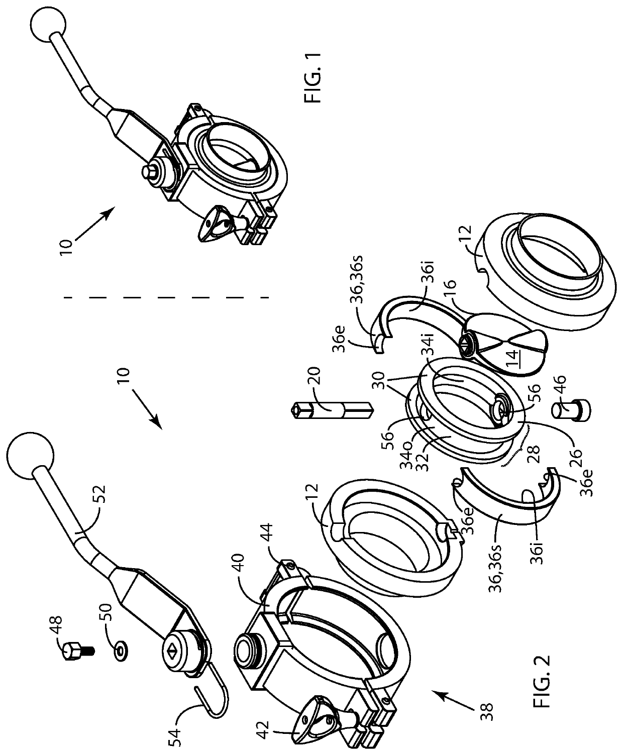
[0048]FIG. 1 is a perspective drawing of an embodiment 10 of the sanitary clean-in-place butterfly valve of this invention. Butterfly valve 10 is shown in FIG. 1 fully assembled and in a fully-closed position. FIG. 2 is an exploded perspective view of butterfly valve 10. Butterfly valve 10 includes a valve housing 12 which has two identical sections which in assembled form are clamped together by a valve clamp assembly 38. Clamp assembly 38 includes a clamp body 40 surrounding valve housing 12 and which is configured to clamp the two sections of valve housing 12 together when butterfly valve 10 is fully a...


PUM


Abstract

An improved butterfly valve having (a) a valve housing, (b) a valve-plate having a peripheral edge located in a central plane when in a fully-closed position, (c) a valve stem configured to rotate the valve-plate about an axis parallel to the central plane to control flow through the valve, and (d) a valve seat configured to engage the peripheral edge to form a seal when the valve-plate is in closed positions, the improvement wherein the valve seat comprises (1) a resilient sealing member having an inward valve-seating surface engaging the peripheral edge therearound and an opposite outward surface; and (2) a ring structure: (i) having an inner surface adjacent to the outward surface; (ii) having the valve stem passing therethrough along the axis; (iii) divided into two sub-ring portions adjacent to each other with valve-stem-adjacent ends; and (iv) sized to permit central-plane-parallel relative sub-ring-portion displacement perpendicular to the axis, thereby lowering valve actuation force.

Description

FIELD OF THE INVENTION[0001]This invention is related generally to the field of valves for sampling, shut-off and flow control, and more particularly to such valves which are used in applications involving high levels of sanitation.BACKGROUND OF THE INVENTION[0002]Disc valves, often called butterfly valves, are used in a wide variety of processes to provide flow control or shut-off at various points within a process system. Some of these applications, such as pharmaceutical and food processing, require extremely high levels of sanitation and sterilization. Many of the valves currently used are difficult to clean while they are installed in the system and thus have to be removed, disassembled, cleaned and then returned to the system in order to achieve and / or maintain the required levels of sanitation and sterilization. These cleaning steps consume a significant amount of time and reduce the overall system productivity which can be realized in such a system.[0003]Current prior art di...

Claims


Application Information

Patent Timeline
Patent Type & Authority Applications(United States)
IPC IPC(8): F16K1/226F16K27/02
CPCF16K1/2265F16K27/0218
Inventor THOMPSON, DONOVAN S.
Owner INOVANCE INC
Why Eureka
Try Eureka