
Rotating tool for double-sided friction stir welding, double-sided friction stir welding apparatus, and double-sided friction stir welding method

a technology of rotating tools and friction stirs, which is applied in the direction of welding apparatus, metal-working equipment, manufacturing tools, etc., can solve the problems of insufficient plastic flow, weld failure, and the welding technique does not consider any application to welding metal plates, so as to reduce increase the length of each vortex

Pending Publication Date: 2021-01-28
JFE STEEL CORP
View PDF14 Cites 1 Cited by
  • Summary
  • Abstract
  • Description
  • Claims
  • Application Information

AI Technical Summary

Benefits of technology

The present invention relates to rotating tools used in manufacturing processes. The invention provides improved tools that have non-symmetrical, stepped portions on the end portions of the tools. These steps help to prevent metal material from flowing out of the tool during the manufacturing process, resulting in a more desirable surface appearance. The non-symmetrical, stepped portions are also designed to prevent the welded portion from having decreased thickness and forming burrs. Additionally, the patent describes a method for forming the stepped portions that ensures the optimal plastic flow of the metal material during the manufacturing process. Overall, the invention provides better tools with more desirable surfaces for use in manufacturing processes.

Problems solved by technology

However, an object of each of the techniques disclosed in Patent Literatures 6 and 7 is to reinforce a welded portion or to harden a metal surface, and these techniques do not consider any application to welding of metal plates.
Thus, in the case where the above-mentioned rotating tool of the related art is used for welding metal plates, there is a possibility that sufficient plastic flow will not be obtained in a plate-thickness direction, which in turn leads to a weld failure.
In addition, an object of each of the techniques disclosed in Patent Literatures 8 to 11 is to weld metal plates by a friction stir method, and these techniques do not consider any application to a double-sided friction stir welding method.
In other words, in Patent Literatures 8 to 11, there is no disclosure of an appropriate relationship between the diameter of an end portion of a tool and the thickness of metal plates which are to be welded together in the double-sided friction stir welding method, and thus, there is a possibility that a indefective joint will not be obtained.

Method used


Image

  • Rotating tool for double-sided friction stir welding, double-sided friction stir welding apparatus, and double-sided friction stir welding method
  • Rotating tool for double-sided friction stir welding, double-sided friction stir welding apparatus, and double-sided friction stir welding method
  • Rotating tool for double-sided friction stir welding, double-sided friction stir welding apparatus, and double-sided friction stir welding method

Examples


first embodiment

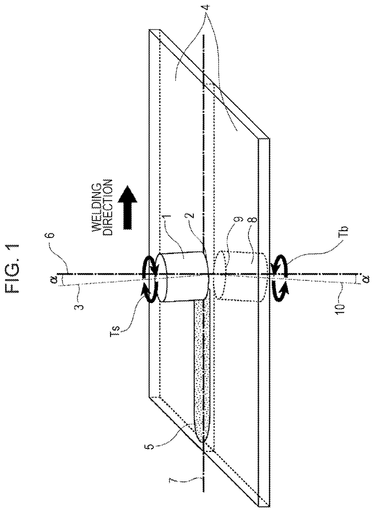
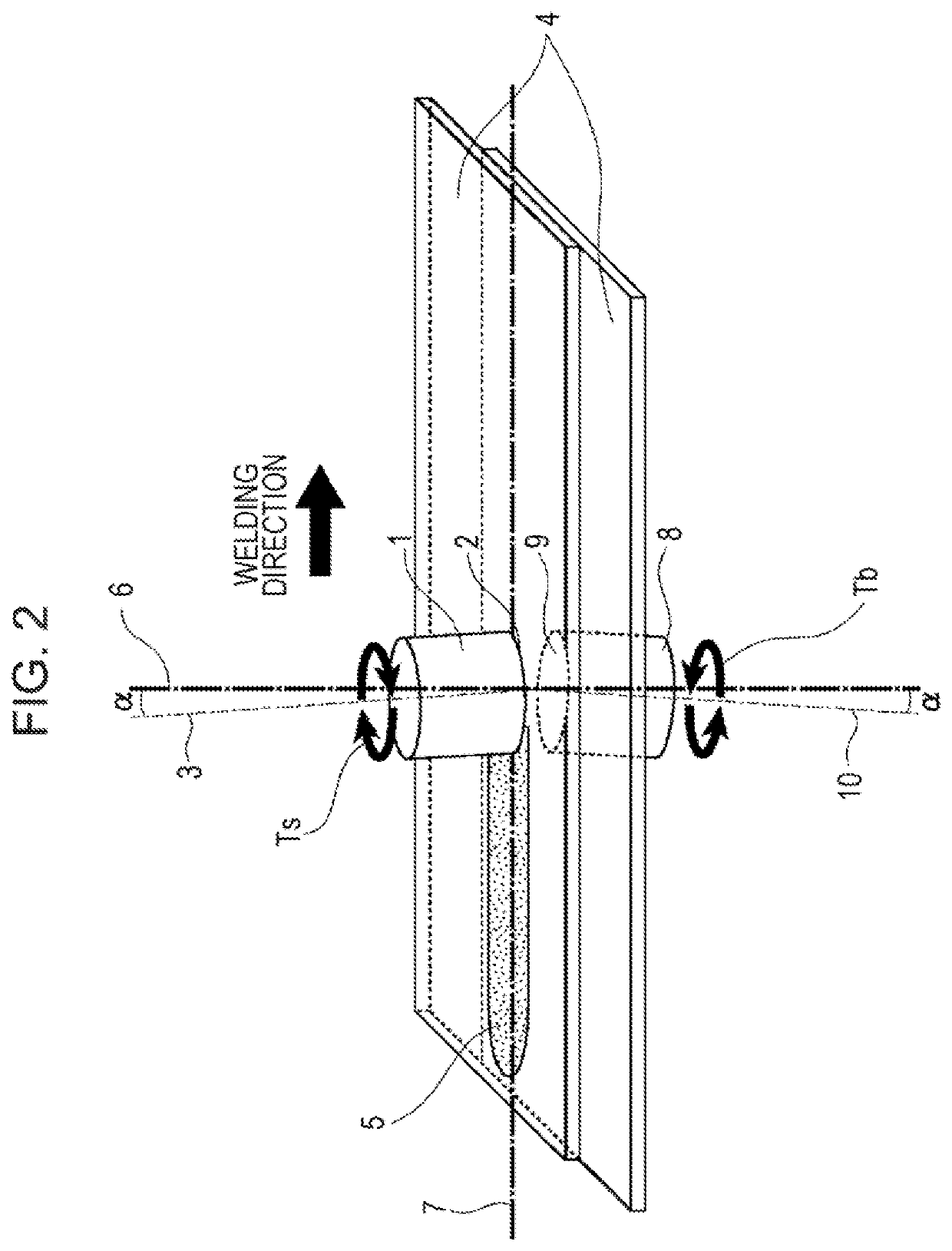
[0081]As illustrated in FIG. 5(a) and FIG. 5(b), each of the rotating tools 1 and 8 according to the first embodiment of the present invention ends with circular peripheries, and each of these ends is formed of simply the end portion 11 having the planar shape 11a. Each of the end portions 11 formed in the planar shape has an end surface that comes into contact with the metal plates and that is formed of a single planar surface perpendicular to the rotation axis of a corresponding one of the rotating tools 1 and 8. Unlike a rotating tool of the related art, each of the end surfaces does not have a probe protruding toward the metal plates. In addition, as illustrated in FIG. 5(b), in each of the rotating tools 1 and 8, the above-mentioned vortex-shaped (spiral-shaped) stepped portions 12, which extend in the direction opposite to the rotation direction, can be formed in one or more tiers in the end portion 11. Note that the step portions 12b or the groove portions 12c, which have bee...

second embodiment

[0082]As illustrated in FIGS. 6(a) and 6(b), the rotating tools 1 and 8 of the second embodiment have circular ends each of which is formed of only the end portion 11 having the convex curved shape 11b, and these ends of the rotating tools are convexed. Although a rotating tool of the related art includes a probe protruding toward metal plates and has a discontinuous shape formed of a shoulder portion and the probe, each of the end portions 11 having the convex curved shape has a continuous shape without having a probe and forms an approximately uniform inclined surface. In other words, each of the end portions 1 having the convex curved shape has an end surface that comes into contact with the metal plates and that is formed of a single curved surface (a parabolic surface, a prolate surface, or a spherical surface) being convexed in the direction toward the center, and the end surface forms a curve having an approximately uniform radius of curvature in a cross-sectional shape inclu...

third embodiment

[0085]As illustrated in FIGS. 7(a) and 7(b), the rotating tools 1 and 8 of the third embodiment have circular ends each of which is formed of simply the end portion 11 having the concave curved shape 11c, and these ends of the rotating tools are concaved. Although a rotating tool of the related art includes a probe protruding toward metal plates and has a discontinuous shape formed of a shoulder portion and the probe, each of the end portions 11 having the concave curved shape has a continuous shape without having a probe and forms an approximately uniform inclined surface. In other words, each of the end portions 1 having the concave curved shape has an end surface that comes into contact with the metal plates and that is formed of a single curved surface (a parabolic surface, a prolate surface, or a spherical surface) being concaved in the direction toward the center, and the end surface forms a curve having an approximately uniform radius of curvature in a cross-sectional shape i...


PUM

PropertyMeasurementUnit
diameteraaaaaaaaaa
thicknessaaaaaaaaaa
inclination angleaaaaaaaaaa

Abstract

Disclosed are rotating tools for double-sided friction stir welding that are applied to double-sided friction stir welding, which is a technique for welding two metal plates by rotating a pair of rotating tools, which oppose each other, in opposite directions, a double-sided friction stir welding apparatus that uses the rotating tools, and a double-sided friction stir welding method. A pair of rotating tools for double-sided friction stir welding that are used in double-sided friction stir welding, which is a technique for welding metal plates by using a pair of rotating tools that are each disposed on one of first and second surfaces of an unwelded portion of the metal plates such that the rotating tools rotate in opposite directions, include end portions each of which is formed in a circular and planar shape. The end portions are each made of a material harder than the metal plates.

Description

CROSS REFERENCE TO RELATED APPLICATIONS[0001]This is the U.S. National Phase application of PCT / JP2019 / 011734, filed Mar. 20, 2019, which claims priority to Japanese Patent Application No. 2018-052622, filed Mar. 20, 2018 and Japanese Patent Application No. 2019-005166, filed Jan. 16, 2019, the disclosures of these applications being incorporated herein by reference in their entireties for all purposes.FIELD OF THE INVENTION[0002]The present invention relates to a rotating tool for double-sided friction stir welding that is applied to double-sided friction stir welding, which is a technique for welding two metal plates by rotating a pair of rotating tools, which oppose each other, in opposite directions, a double-sided friction stir welding apparatus that uses the rotating tools for double-sided friction stir welding, and a double-sided friction stir welding method.BACKGROUND OF THE INVENTION[0003]Patent Literature 1 discloses a technique for welding a pair of members such as metal ...

Claims


Application Information

Patent Timeline
Patent Type & Authority Applications(United States)
IPC IPC(8): B23K20/12
CPCB23K20/1255B23K20/1225B23K20/125B23K20/123
Inventor MATSUSHITA, MUNEOIKEDA, RINSEIMATSUDA, HIROSHIYAMAGISHI, DAIKI
Owner JFE STEEL CORP
Learn More