Digital 3D infrared slit lamp with pupil and retina intensity measurement

Active Publication Date: 2021-01-28
MCWHERTER IAN
View PDF0 Cites 0 Cited by
  • Summary
  • Abstract
  • Description
  • Claims
  • Application Information

AI Technical Summary

Benefits of technology

The patent describes a device that can examine different parts of the eye using different colored lights. The device includes two LEDs that produce visible light and another LED that produces infrared light. The wavelength of the lights can also be adjusted to better evaluate specific parts of the eye. This device can help doctors better diagnose and treat diseases of the eye.

Problems solved by technology

This is due to limitations from reflections from ocular structures but also due to the amount of light that a patient can comfortably tolerate during an examination.

Method used


Image

  • Digital 3D infrared slit lamp with pupil and retina intensity measurement
  • Digital 3D infrared slit lamp with pupil and retina intensity measurement
  • Digital 3D infrared slit lamp with pupil and retina intensity measurement

Examples


Embodiment Construction

[0046]While various aspects and features of certain embodiments have been summarized above, the following detailed description illustrates a few exemplary embodiments in further detail to enable one skilled in the art to practice such embodiments. The described examples are provided for illustrative purposes and are not intended to limit the scope of the invention.

[0047]In the following description, for the purposes of explanation, numerous specific details are set forth in order to provide a thorough understanding of the described embodiments. It will be apparent to one skilled in the art, however, that other embodiments of the present invention may be practiced without some of these specific details. Several embodiments are described herein, and while various features are ascribed to different embodiments, it should be appreciated that the features described with respect to one embodiment may be incorporated with other embodiments as well. By the same token, however, no single fea...


PUM


Abstract

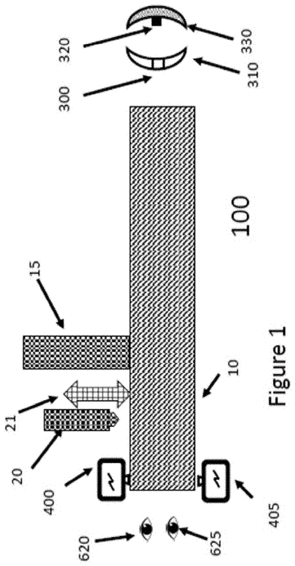
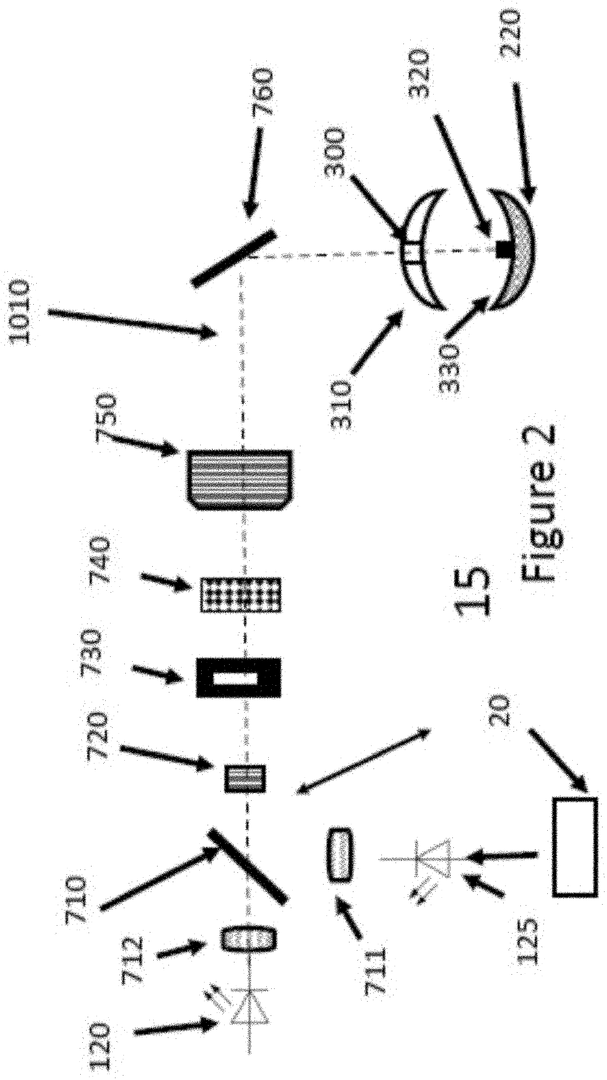
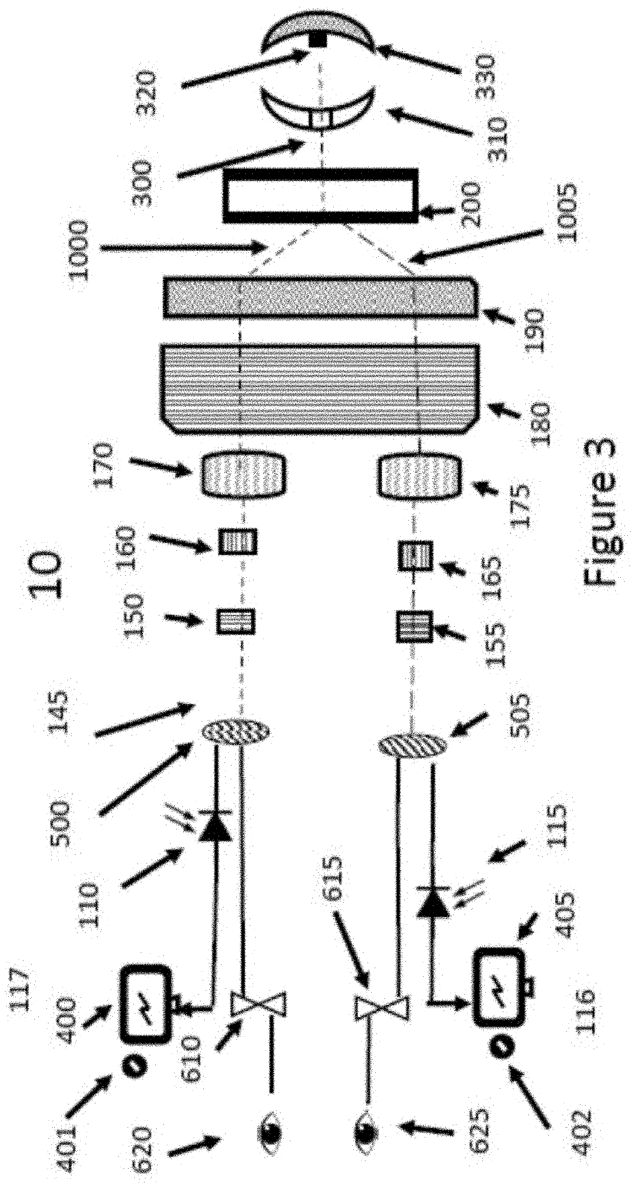
The invention relates to a device and method of ophthalmic diagnosis of lesions on retina utilizing a slit lamp apparatus with a pupil reader and at least one visible LED and one Infrared LED to detect a lesion on the retina of an eye.

Description

COPYRIGHT STATEMENT[0001]A portion of the disclosure of this patent document contains material that is subject to copyright protection. The copyright owner has no objection to the facsimile reproduction by anyone of the patent document or the patent disclosure as it appears in the Patent and Trademark Office patent file or records, but otherwise reserves all copyright rights whatsoever.[0002]Trademarks used in the disclosure of the invention and the applicants make no claim to any trademarks referenced.CROSS-REFERENCE TO RELATED APPLICATION[0003]This application claims priority from U.S. provisional patent application Ser. No. 62 / 636,867, filed Mar. 1, 2018 entitled Digital 3D slit lamp, U.S. patent application Ser. No. 15 / 981,930, filed May 17, 2018 entitled Digital 3D Infrared Slit lamp with pupil measurement and U.S. patent application Ser. No. 16 / 792,833, filed Feb. 17, 2020 entitled Digital 3D Infrared Slit lamp with pupil measurement which are hereby incorporated by reference ...

Claims


Application Information

Patent Timeline
IPC IPC(8): A61B3/135A61B3/11A61B3/00A61B3/14
CPCA61B3/135A61B3/14A61B3/0008A61B3/112A61B3/12
Inventor MCWHERTER, IAN
Owner MCWHERTER IAN
Why Eureka
Try Eureka