
Patsnap Eureka
For R&D, Patsnap Eureka makes reading and utilizing patents & technical documents easy.
Patsnap Eureka AIR
Designed for self-driven R&D workflows. Generate viable solutions, solve complex R&D challenges, empower your innovation with AI.

Patsnap Eureka Materials
Designed for material experts only. Revolutionize your material R&D, from search, analyze, to developing new materials.

TechResearch
Generate reliable direction feasibility study reports for your R&D in just a few steps.

TechSeek
Discover and master advanced knowledge NOW. Basics, ideas, possibilities, all at once.

TechMind
As an expert in R&D Theories, TechMind can generates customized viable solutions instantly.

TechRisk
Analyze your overall solution with one click, know your potential R&D risks in advance.

TechMonitor
Get weekly tech updates, stay abreast of the latest tech innovations and key insights.
Vehicle securing apparatus
a technology for securing apparatuses and vehicles, applied in the direction of apparatus for force/torque/work measurement, instruments, brake systems, etc., can solve the problems of reducing the flexibility (extendability) of position, difficult to arrange vehicle securing apparatuses as desired, and difficult to attach a pulling force sensor, etc., to achieve the effect of enhancing the flexibility of pulling the test vehicl
- Summary
- Abstract
- Description
- Claims
- Application Information
AI Technical Summary
Benefits of technology
Problems solved by technology
Method used
Image

Examples
first embodiment
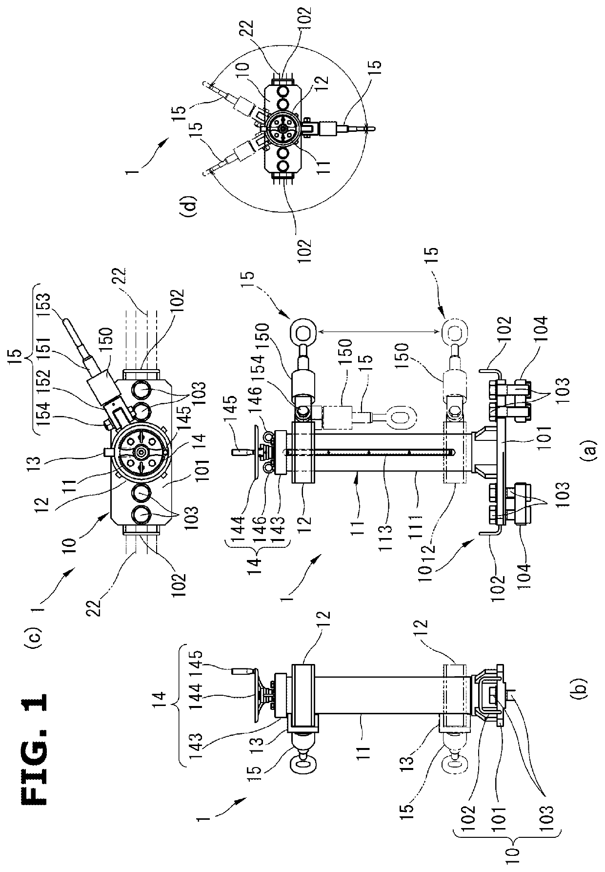
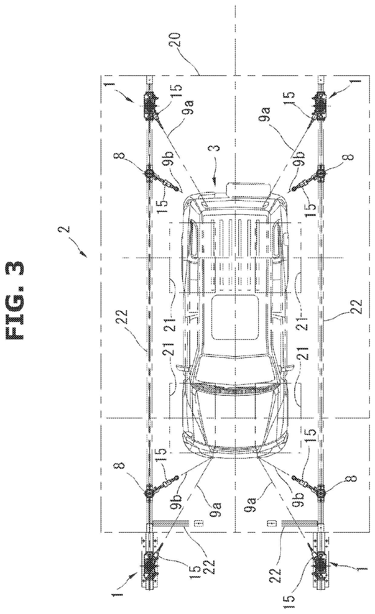
[0035][First Embodiment]FIG. 1 exemplarily shows a vehicle securing apparatus 1 which is structured to pull a test vehicle 3 and thereby secure the test vehicle 3 on a pit cover 20 of a vehicle testing device 2 shown in FIG. 3, wherein a road wheel not shown of the test vehicle 3 is placed on a roller not shown that is exposed through a roller opening 21 of the pit cover 20.
[0036]In particular, the vehicle securing apparatus 1 is structured to be mounted to an arbitrary position on a slide rail 22 placed on the pit cover 20 or outside the pit cover 20 as shown exemplarily in FIG. 3, wherein the height of a support point of the pulling and the direction of the pulling can be adjusted within respective predetermined ranges.
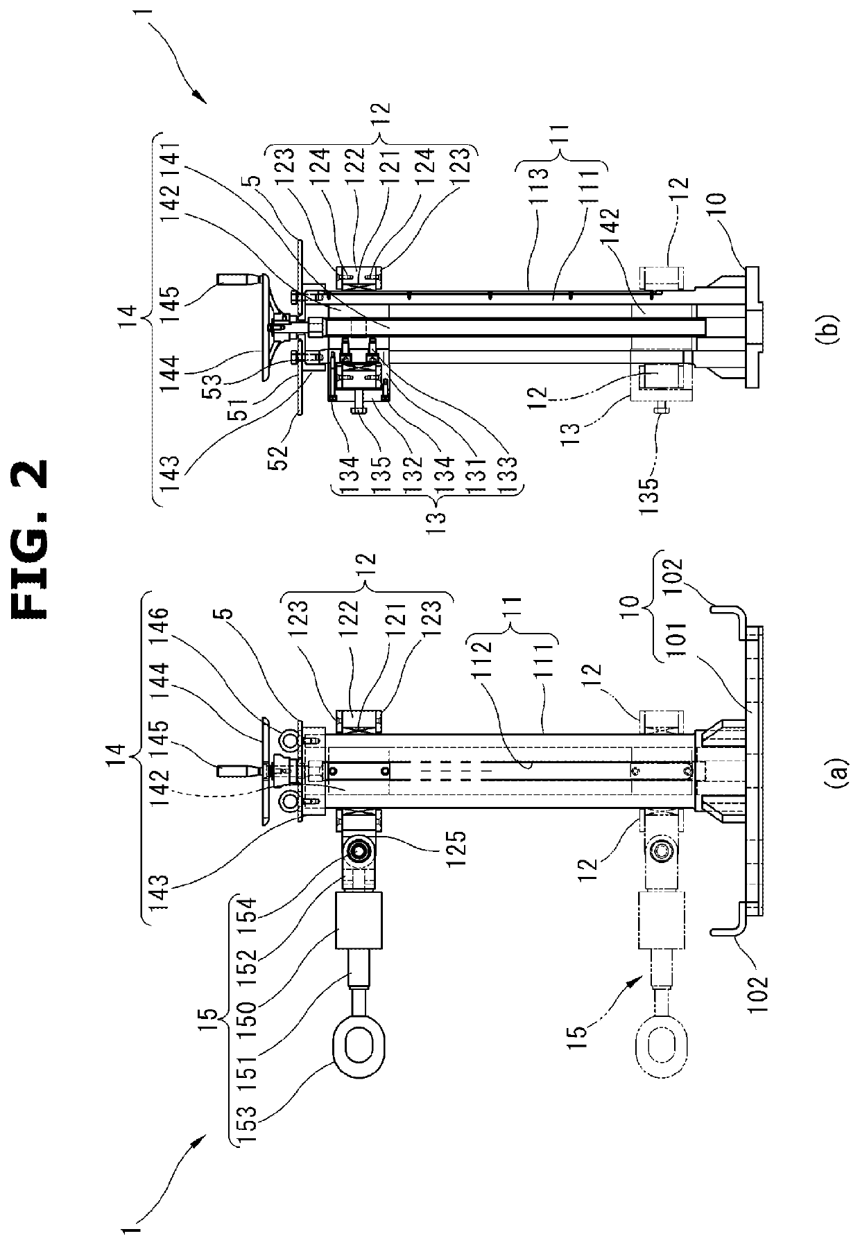
[0037]1> As shown in FIGS. 1 and 2, the vehicle securing apparatus 1 includes a pedestal 10, a column 11, a traveling and rotating part 12, a fixing fitting 13, and a vertical operation part 14.
[0038]10> The pedestal 10 is structured to be mounted to an arbitrary p...
second embodiment
[0072][Second Embodiment] The fitting coupling part 125 of the traveling and rotating part 12 shown in FIG. 1 may be connected to the chain 9a via the coupling fitting 15 provided with no load cell 150. For example, the coupling fitting 15 of this embodiment is a hook, shackle, etc.
[0073]The vehicle securing apparatus 1 including the coupling fitting 15 of the present embodiment makes it possible to support a test that requires no measurement of the pulling force of the vehicle securing apparatus 1, in addition to the effects of the first embodiment. It is apparent that the same effect can be obtained even if the load cell 150 is structured to be detached from the coupling fitting 15 in the first embodiment.
third embodiment
[0074][Third Embodiment]FIG. 4 shows a vehicle securing apparatus 1 which is further provided with casters 4 and a caster movement handle 5 as compared to the vehicle securing apparatus 1 of the first embodiment.
[0075]The pair of casters 4 are attached to a longitudinally-extending edge portion of the pedestal 10 so as to allow the vehicle securing apparatus 1 to be moved. The caster 4 of this embodiment includes: a bracket 41 structured to be attached to the longitudinally-extending edge portion of the pedestal 10 with fixing bolts 42; and a wheel 40 rotatably supported by the bracket 41.
[0076]The caster movement handle 5 is attached to the column 11, and is gripped for movement of the vehicle securing apparatus 1. The caster movement handle 5 of this embodiment includes: a handle body 51 having a rectangular plate shape and attached to the lid 143 of the vertical operation part 14 by fixing bolts 53; and a pair of grips 52 extending in the lateral direction of the handle body 51....
PUM
 Abstract
Description
Claims
Application Information
 - R&D Engineer
- R&D Manager
- IP Professional
- Industry Leading Data Capabilities
- Powerful AI technology
- Patent DNA Extraction
Browse by: Latest US Patents, China's latest patents, Technical Efficacy Thesaurus, Application Domain, Technology Topic, Popular Technical Reports.
© 2024 PatSnap. All rights reserved.Legal|Privacy policy|Modern Slavery Act Transparency Statement|Sitemap|About US| Contact US: help@patsnap.com