
System and method for non-invasive ventilation

a non-invasive ventilation and system technology, applied in the field of systems and methods for non-invasive ventilation, can solve the problems of user intolerance to the pressure of the patient interface, poor patient compliance, user intolerance, etc., and achieve the effect of increasing the resistance of the primary flow path, and increasing the resistance to gas flow

Pending Publication Date: 2021-01-21
FISHER & PAYKEL HEALTHCARE LTD
View PDF0 Cites 0 Cited by
  • Summary
  • Abstract
  • Description
  • Claims
  • Application Information

AI Technical Summary

Benefits of technology

The control assembly described in this patent is designed to regulate the flow of respiratory gas delivered to a patient. It can open or restrict the flow of gas through the primary path, based on the pressure on either the gas source or patient interface side. This assembly can help ensure that the respiratory gas is flowing at the right pressure and flow rate for the patient, which can improve respiratory function and patient outcomes.

Problems solved by technology

Challenges to the success of CPAP therapies may include, among other things, user intolerance to patient interface pressures (manifested by, for example, localized pain and / or pressure sores) and poor patient compliance (which may be caused by elevated therapy pressures and its potential downstream effects).
Challenges to the success of Bi-level therapy may include, among other things, user intolerance to patient interface pressures (manifested by, for example, localized pain and / or pressure sores), patient-ventilator asynchrony, and poor patient compliance (which may be caused by elevated therapy pressures and its potential downstream effects).
Although high therapy pressure is a primary mechanism by which noninvasive ventilation improves alveolar gas exchange for patients, it may require conditions that promote therapy failure.
For example, ventilating at higher pressures demands more effective sealing of mask to the patient's face, which generally requires high headgear tension and leads to high forces being applied to the patient's skin.
Over time, such high pressure may cause skin break down (pressure sores) which can lead to severe patient discomfort as well as penalties for the hospitals in some cases.
Ultimately, these side effects can often result in poor patient tolerance and failure of the therapy.

Method used


Image

  • System and method for non-invasive ventilation
  • System and method for non-invasive ventilation
  • System and method for non-invasive ventilation

Examples


first embodiment

[0155]FIGS. 7A-7C show a flap valve with a centrally located aperture. The mounting structure is surrounded by six radially disposed flaps each equidistantly spaced around the perimeter of the mounting surface. The raised lip as shown in FIGS. 7B and 7C provides a locating feature for mounting the flap valve in the primary flow path. Each flap extends away from the central aperture in a direction that is normal to the face of the ring. The flaps are substantially flat and have no curvature. The flaps are radially spaced around the mounting surface with a gap formed between each flap such that they do not contact each other. This gap may correspond with structures used for mounting the flap valve in the primary flow path or structures used to limit the flaps from bending in one direction while allowing for them to bend in a second, opposed direction. Each flap extends equidistantly away from the ring. The distal edges of each flap are curved. In combination, the distal edges of each ...

second embodiment

[0157]FIGS. 7D-7E show a flap valve with a non-centrally located aperture. The aperture is offset towards one side of the flap valve. Three non-uniformly shaped flaps are spaced around the perimeter of the mounting structure. Although the individual flaps are non-uniform, they are shaped and located so that the outside perimeter of the flap valve is substantially circular. The flaps are spaced apart such that they do not contact each other. The flap valve comprises a central, main flap and two smaller side flaps to either side of the central flap. The central flap is larger than each of the side flaps. The central flap is a different shape to the side flaps. The central flap is triangular shaped with a curved distal edge from the mounting structure.

[0158]The embodiment of the one-way valve shown in FIGS. 7F-7G has a curved and inclined flap surface. The embodiment of the one-way valve shown in FIGS. 7H-7I has a flat and inclined flap surface. The embodiment of the one-way valve show...

third embodiment

[0159]FIGS. 7F-7G show a flap valve comprising a centrally located aperture. The raised lip of the mounting structure is surrounded by six uniform and equidistantly spaced flaps. The flaps extend from the mounting structure in two dimensions (upwardly and outwardly). The flaps curve away from the mounting structure. Each flap has a profile that is substantially in the shape of a quarter oval.


PUM


Abstract

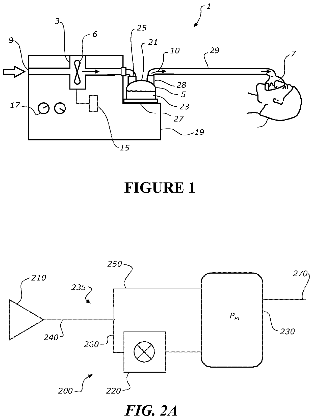
Systems and methods for non-invasive ventilation are provided. The systems may include a gas source that provides breathing gases to a patient through one or more of a primary flow path (PFP) and a flushing flow path (FFP). The system may include a control assembly configured to open and restrict gas flow through the PFP. When the PFP is open, a significant portion of the gas flows through the PFP while the remaining gas flows through the FFP. When the PFP is restricted, a significant portion of the gas flows through the FFP. Increased flow through the FFP may have a high velocity (especially relative to the flow through the PFP). Gas delivered through the FFP may be used to flush dead space. One or both flow paths may contribute to inspiratory positive airway pressure (IPAP), expiratory positive airway pressure (EPAP), and / or positive end expiratory pressure (PEEP).

Description

BACKGROUNDField[0001]The application relates generally to systems and methods for non-invasive ventilation, and more specifically, relates to various control assemblies for controlling airflow and / or delivery to a patient interface and, ultimately, to a patient.Description of the Related Art[0002]Respiratory therapy systems are typically used for the treatment of respiratory conditions such as, for example, obstructive sleep apnea (OSA) or chronic obstructive pulmonary disease (COPD). Respiratory therapy systems typically deliver heated and humidified gases for various medical or therapy procedures, including respiratory treatment. Such systems can be configured to control temperature, humidity and flow rates.[0003]Respiratory therapy systems generally include a gas source (such as a ventilator, a CPAP generator or other flow generator), a patient interface worn by a patient and a breathing circuit that connects the gas source to the patient interface. Respiratory therapy systems ge...

Claims


Application Information

Patent Timeline
IPC IPC(8): A61M16/20A61M16/10A61M16/08A61M16/16
CPCA61M16/206A61M16/208A61M16/1015A61M2205/3368A61M16/0883A61M16/161A61M2205/3334A61M16/0875A61M16/0666A61M16/0833A61M16/06A61M39/24A61M39/105A61M2039/246A61M2205/3344A61M16/024A61M16/0066A61M16/16A61M2205/502A61M2202/0225A61M16/0866A61M2205/3331A61M16/0816A61M16/201A61M16/204A61M16/0858A61M2210/1053A61M2016/0039A61M2016/0027A61M2210/0618A61M2202/0085A61M2210/005
Inventor ZOELLNER, SASCHA KRISTOPHERPRENTICE, BHAVNANIHOTTE, JOSEPH JULESNELSON, GRANT LEIGHGORDON, JAMES ALEXANDERO`NEILL, BRENDAN
Owner FISHER & PAYKEL HEALTHCARE LTD
Learn More