
Ophthalmic incisional procedure instrument and method

a technology of incisional instruments and incisions, applied in the field of incisional instruments for surgical incisions, can solve problems such as blurry or distorted vision, improper focus, and distortion of vision, and achieve the effects of reproducibility, efficient and accura

Inactive Publication Date: 2021-01-14
EYEMDENG LLC
View PDF2 Cites 1 Cited by
  • Summary
  • Abstract
  • Description
  • Claims
  • Application Information

AI Technical Summary

Benefits of technology

The instrument enables efficient, accurate, and reproducible LRIs, reducing reliance on surgeon skill and cost, while providing improved vision outcomes for patients without the need for glasses or contact lenses.

Problems solved by technology

These mismatched curvatures cause images to not be properly focused on the retina, resulting in blurry or distorted vision.
Originally, incisions to correct corneal astigmatism were made in the para-central cornea, but over the years, ophthalmologists have gradually placed these incisions further from the center of the eye because of problems with healing, predictability, and glare.
A cataract is another very common optical condition in which the natural lens of the eye becomes cloudy, causing distorted vision.
However, this method of manual incision is generally reliant on the surgeon to perform LRIs at the correct depth, length, and curvature.
However, the costs associated with using femtosecond lasers tend to be relatively high.
Additionally, some current literature suggests that the use of such lasers does not improve outcomes in cataract surgery.
However, the Universal Limbal Relaxing Incision Guide does not attach or anchor to the eye during the surgical procedure, making the accuracy of the LRIs reliant on the surgeon or an assistant holding the instrument in the proper position without moving.

Method used


Image

  • Ophthalmic incisional procedure instrument and method
  • Ophthalmic incisional procedure instrument and method
  • Ophthalmic incisional procedure instrument and method

Examples


Embodiment Construction

I. Introduction and Environment

[0025]As required, detailed aspects of the present invention are disclosed herein, however, it is to be understood that the disclosed aspects are merely exemplary of the invention, which may be embodied in various forms. Therefore, specific structural and functional details disclosed herein are not to be interpreted as limiting, but merely as a basis for the claims and as a representative basis for teaching one skilled in the art how to variously employ the present invention in virtually any appropriately detailed structure.

[0026]Certain terminology will be used in the following description for convenience in reference only and will not be limiting. For example, up, down, front, back, right, and left refer to the invention as orientated in the view being referred to. The words “inwardly” and “outwardly” refer to directions toward and away from, respectively, the geometric center of the aspect being described and designated parts thereof. Additionally, ...


PUM


Abstract

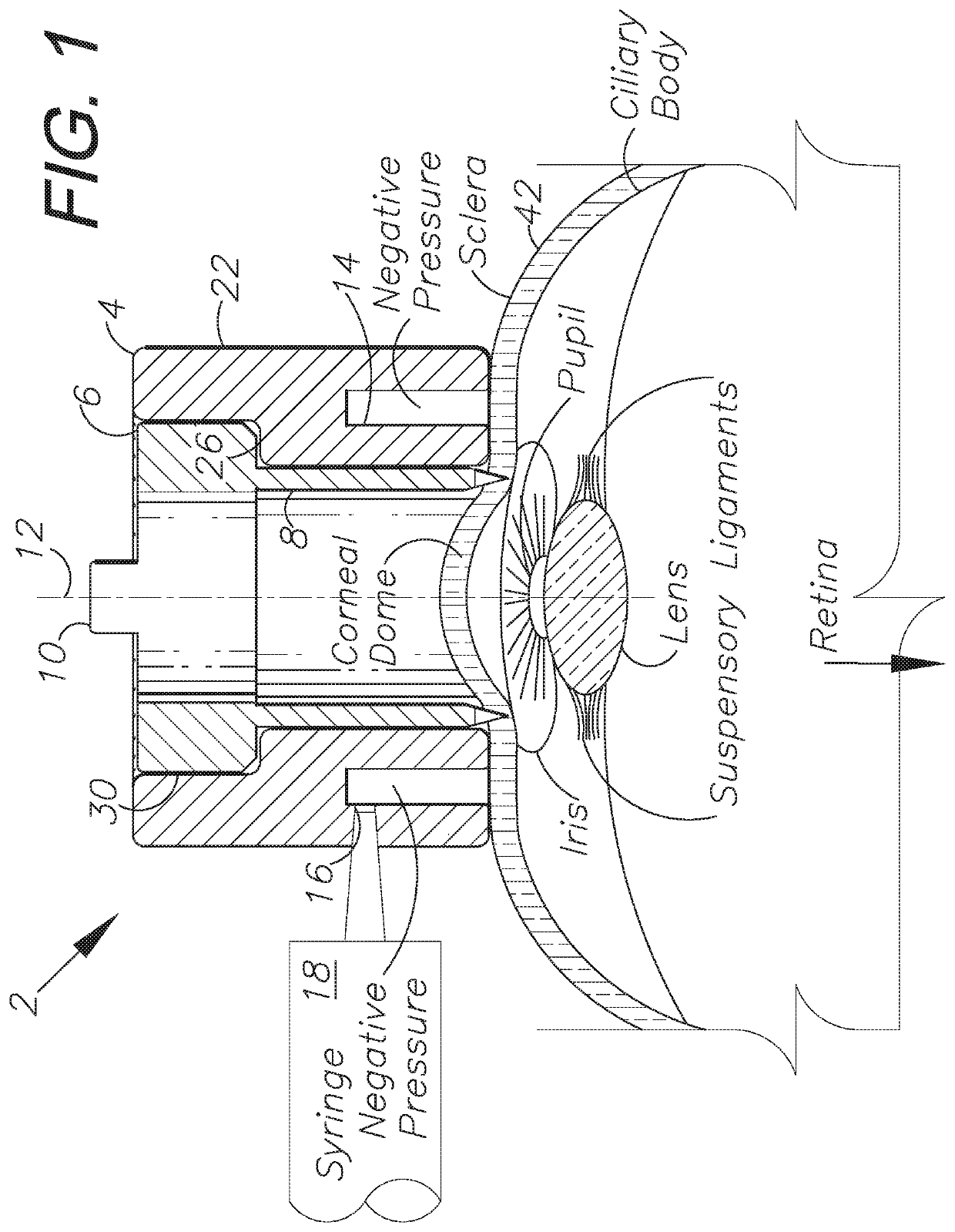
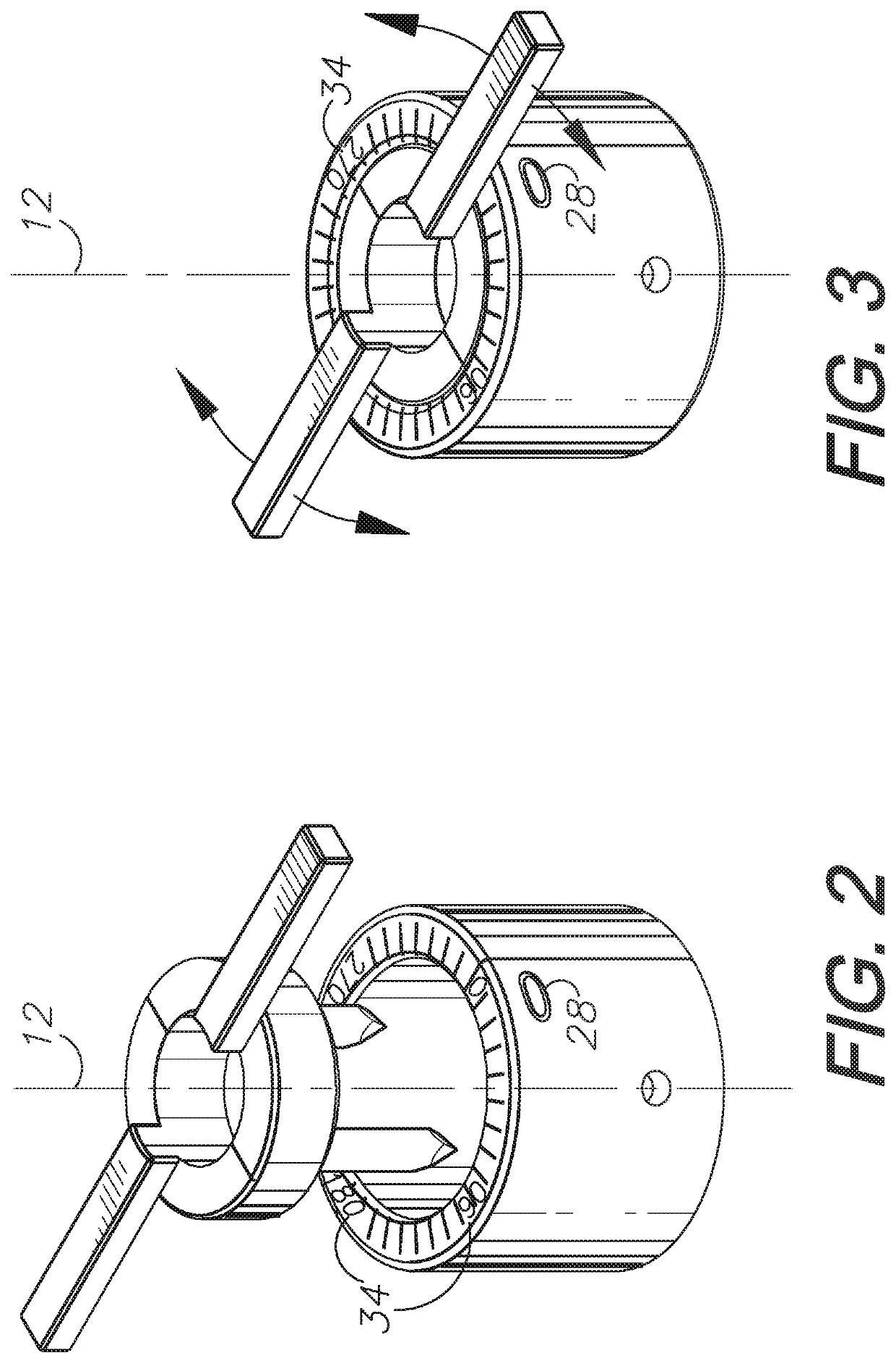
An incisional instrument and method of use for creating accurate, reproducible surgical incisions. An exemplary embodiment includes an incisional instrument configured for attachment to a patient's eye and for use performing arcuate limbal relaxing incisions (LRIs). The incisional instrument is made up of two coaxial, interconnecting pieces: a docking piece and a cutting piece. The docking piece includes a suction mechanism and is configured for being secured to a patient's eye just outside the corneal limbus. The cutting piece is configured to fit flush within the docking piece and includes cutting blades and one or more handles for rotating the cutting piece relative to the docking piece. When assembled, the cutting blades extend beyond the proximal end of the docking piece by a length equal to the desired depth of LRIs to be cut. The incisional instrument further includes measurement markings for properly positioning and measuring incisions.

Description

CROSS-REFERENCE TO RELATED APPLICATION[0001]This application is a continuation of and claims priority in U.S. Non-Provisional patent application Ser. No. 15 / 899,784, filed Feb. 20, 2018, which claims priority in U.S. Provisional Patent Application No. 62 / 460,660, filed Feb. 17, 2017, both of which are incorporated herein by reference.BACKGROUND OF THE INVENTION1. Field of the Invention[0002]The present invention relates generally to an incisional instrument and method for performing surgical incisions, and more specifically to an ophthalmic incisional instrument for surgical correction of astigmatism and a corresponding method of performing a surgical procedure.2. Description of the Related Art[0003]Astigmatism is a type of visual refractive error caused by aberrant meridians of curvature around an otherwise spherical cornea or lens. These mismatched curvatures cause images to not be properly focused on the retina, resulting in blurry or distorted vision. Other symptoms of astigmati...

Claims


Application Information

Patent Timeline
Patent Type & Authority Applications(United States)
IPC IPC(8): A61F9/013
CPCA61F9/0133A61B2017/306A61B2217/005A61F9/0136
Inventor POLE, CHRISTOPHER J.PEDDADA, KRISHI
Owner EYEMDENG LLC
Learn More