
Power cable end treatment device

a technology for power cables and end caps, which is applied in metal working equipment, laser beam welding equipment, manufacturing tools, etc., can solve the problems of reducing the user's exposure to toxic fumes and heavy tools, and achieves the improvement of user friendliness, improved durability of kinematic devices, and improved motor durability.

Pending Publication Date: 2021-01-07
RELIBOND APS
View PDF2 Cites 0 Cited by
  • Summary
  • Abstract
  • Description
  • Claims
  • Application Information

AI Technical Summary

Benefits of technology

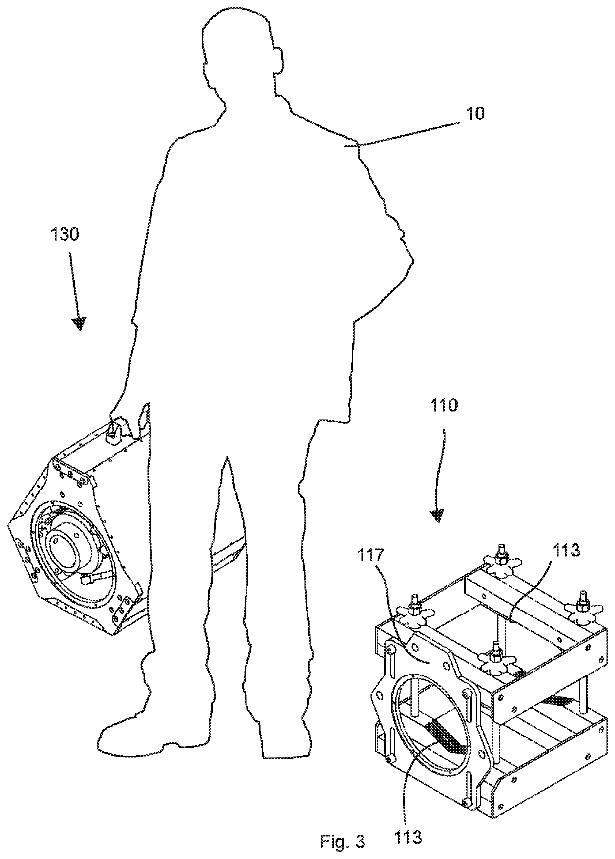
The invention is a cable treatment device that allows for fully controllable motion for cable end treatments, such as cable joints and terminations. This allows for repeatable, high-quality treatment, avoiding faulty connections that may require repairs. The device is also user-friendly, portable, and improves treatment quality. It reduces user exposure to tools and toxic fumes, and the treatment process takes place in an enclosed and exhaustured environment. Overall, the cable treatment device provides a controlled and safe way to treat cable ends, resulting in improved durability and reliability.

Problems solved by technology

Even further, treatment of a cable end using the cable treatment device decreases the user exposure to heavy tools and toxic fumes, as they can leave while the device treats the cable end, and the process can take place in an enclosed and exhausted environment while the device treats the cable end.

Method used


Image

  • Power cable end treatment device
  • Power cable end treatment device
  • Power cable end treatment device

Examples


example 2

[0107]More complicated treatments can be performed on the cable end according to the invention. An example treatment is to first mount a modular cable end treatment device. A modular needle hammer tool head is inserted in the tool socket to make the cable end flatter. Afterwards, the modular needle hammer tool head is switched out for a modular cold spraying tool head to build an electrically conductive layer on the end of the newly flattened cable end.

example 3

[0108]A third example of a cable end treatment according to the invention is a preparation treatment. A combined pneumatic / blowtorch tool head is used to blow off coarse particles and burn away impurities depending on surface characteristics. An optical sensor transmits data relating to surface parameters to a processor that evaluates the surface simultaneously with the cleaning treatments to determine which of the tools should treat a given area, as well as informing on the cleanliness of the cable end. The treatment stops when certain optical parameters are met.

example 4

[0109]A cable end surface is welded while an optical sensor monitors progress and informs on the treatment to correct the welding in real time. It monitors both the quality of the welds themselves as well as potentially any vapour formation that may be indicative of melted polymers in the weld. The information collected along the process is uploaded to a database for providing a report and presenting the quality control.


PUM

PropertyMeasurementUnit
Lengthaaaaaaaaaa
Forceaaaaaaaaaa
Angleaaaaaaaaaa

Abstract

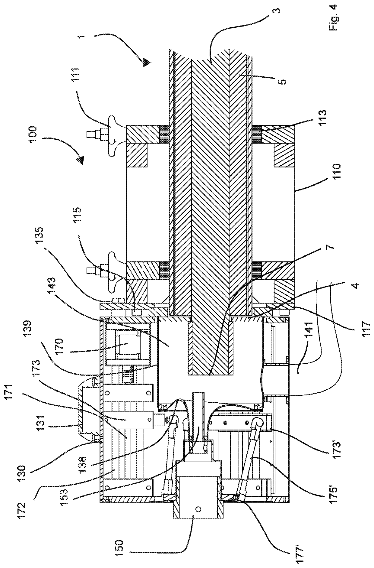
A cable treatment device including: an affixing device for reversibly securing to a circumference of a power cable a kinematic device having attachment structure for attaching to the affixing member, the kinematic device adapted to provide kinematic motion relative to the attachment structure, the kinematic motion being fully controllable through a plurality of force input connections, and a tooling device attached to the kinematic device, the tooling device adapted to receive said kinematic motion, wherein the kinematic device allows the tooling to move cross-sectionally relative to the extension of a power cable secured by the affixing device. Thereby, a well-controlled and reproducible process is achieved, employing a portable device being user friendly, while simultaneously reducing technician exposure to toxic particulates.

Description

FIELD OF THE INVENTION[0001]The current invention relates to a device and method for treatment of power cable ends, especially termination and joining of multi-stranded cables.BACKGROUND OF THE INVENTION[0002]Cables of various sizes and material compositions are used for transportation of electrical current and power. Where the demand for electrical power transmission is high, such as in the power transmission and power distribution systems between a power source and densely populated or industrial areas the required cable dimensions likewise increase. Installation is performed by unrolling cables, followed by burying them underground or pulling them in conduits or ducts. The larger the cables, the shorter the cable length that can be transported on a single cable reel from cable factory to the installation site, necessitating more cable joints. Wth the recent increase in use of aluminium cables, this is exacerbated, as a given cable power transmission requirement necessitates a lar...

Claims


Application Information

Patent Timeline
IPC IPC(8): H01R43/22H01R43/02H02G1/14
CPCH01R43/22H02G1/14H01R43/0263H01R43/28B25H3/006B23K2101/32B23K26/354
Inventor NIELSEN, MARTIN SANDERMICHELSEN, CHRISTIANISAKSEN, SØREN
Owner RELIBOND APS
Learn More