
Radiation Element and Antenna

a radiation element and antenna technology, applied in the field of antennas, can solve the problems of reducing the overall performance of the system, poor isolation between the radiation elements, etc., and achieve the effect of small area

Inactive Publication Date: 2020-12-31
AAC OPTICS SOLUTIONS PTE LTD
View PDF0 Cites 0 Cited by
  • Summary
  • Abstract
  • Description
  • Claims
  • Application Information

AI Technical Summary

Benefits of technology

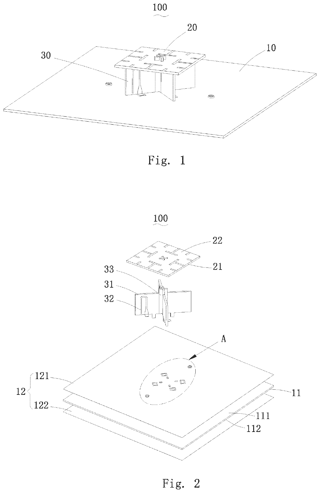
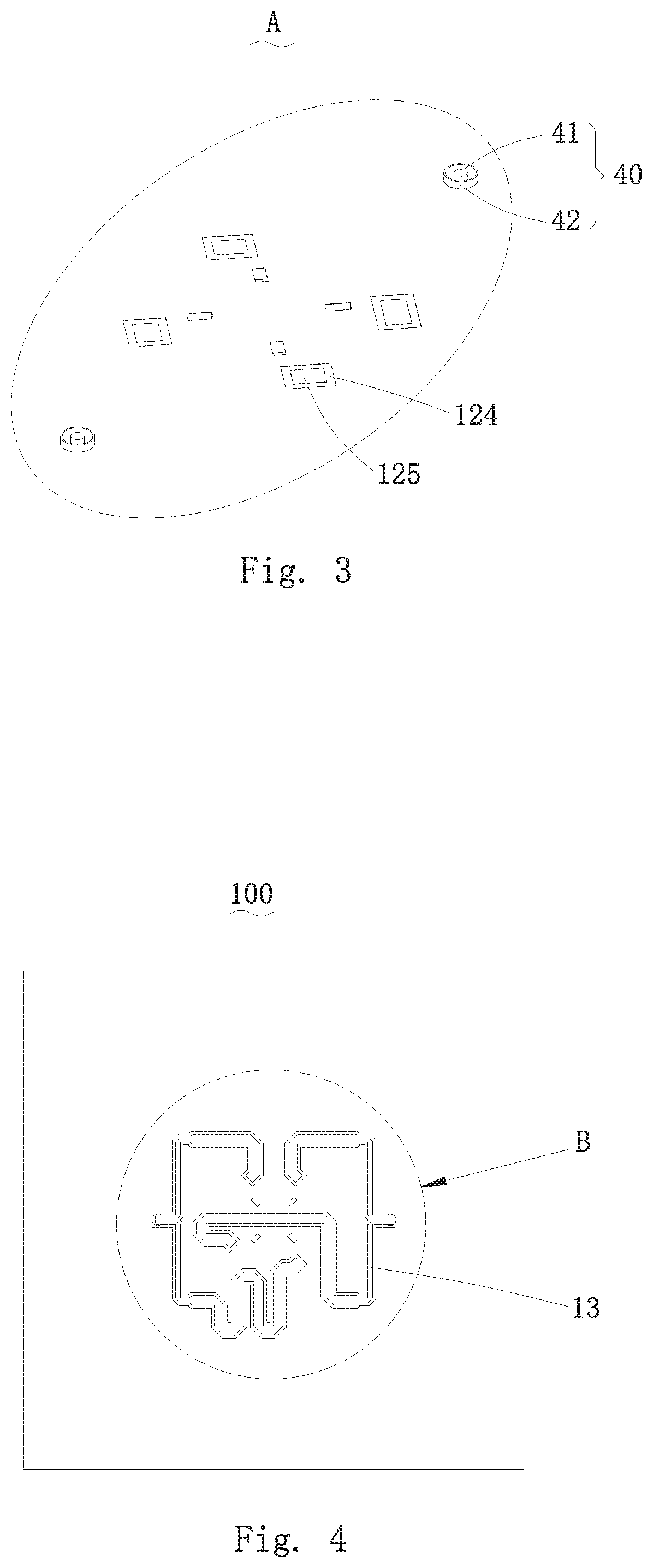
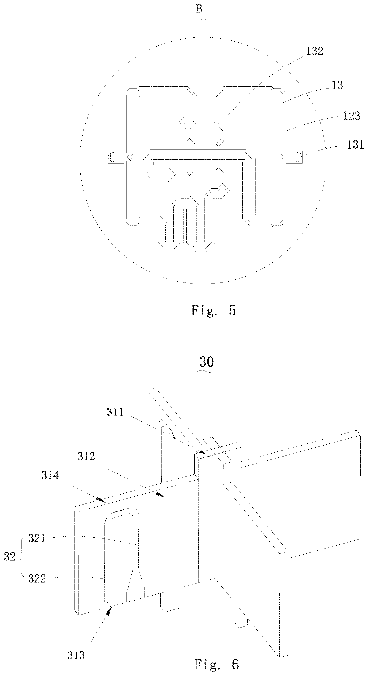
The embodiment describes a radiation element that has a smaller size after a fractal process, resulting in a smaller area and lower operating frequency. This reduces the volume of the antenna and improves isolation between antennas, optimizing the performance of the system. Tests show that a second order fractal can reduce the area of the radiation element by about 20% at the same operating frequency. Higher orders of fractal can result in even smaller areas.

Problems solved by technology

The area of the radiation elements is relatively large, and spacing distances between the radiation elements are limited during array forming, so that the isolation between the radiation elements is relatively poor and the overall performance of a system is reduced.

Method used


Image

  • Radiation Element and Antenna
  • Radiation Element and Antenna
  • Radiation Element and Antenna

Examples


Embodiment Construction

[0029]The present disclosure will hereinafter be described in detail with reference to an exemplary embodiment. To make the technical problems to be solved, technical solutions and beneficial effects of the present disclosure more apparent, the present disclosure is described in further detail together with the figure and the embodiment. It should be understood the specific embodiment described hereby is only to explain the disclosure, not intended to limit the disclosure.

[0030]It is to be noted that all directional indicators in the embodiment of the invention (for example, upper, lower, left, right, front, back, inner, outer, top, bottom and the like) are only used for explaining relative position relationships among parts in some special gesture (for example, shown in the drawings) and so on. If the special gesture changes, the directional indicators also change correspondingly.

[0031]It should also be noted that when an element is referred to as being “fixed” or “disposed” on ano...


PUM


Abstract

The invention provides a radiation element and an antenna. The radiation element is formed by a square board through N-ORDER FRACTAL, wherein N is an integer and is greater than or equal to 3. First hollow grooves are separately formed in the middle parts of four edges of the square board towards the center of the square board. Second hollow grooves are separately formed in the middle parts of the four edges of each first order square towards the center of the first order square. Fractal of a structure formed after the second order fractal is continued to form the N-ORDER FRACTAL according to a second order fractal method. The radiation element provided by the invention has the advantage of small area at the same operating frequency.

Description

FIELD OF THE PRESENT DISCLOSURE[0001]The invention relates to the field of antennas, in particular to a radiation element and an antenna using the radiation element.DESCRIPTION OF RELATED ART[0002]Traditional radiation elements for antennas adopt a conventional geometry design, and the area of the radiation elements needs to be up to about half of wavelengths at operating frequencies. The area of the radiation elements is relatively large, and spacing distances between the radiation elements are limited during array forming, so that the isolation between the radiation elements is relatively poor and the overall performance of a system is reduced.SUMMARY OF THE INVENTION[0003]One of the object of the invention is to provide a radiation element having the advantage of small area at the same operating frequency.[0004]Thus, the invention provides a radiation element applied to an antenna, wherein the radiation element is formed by a square board through N-ORDER FRACTAL; where N is an in...

Claims


Application Information

Patent Timeline
IPC IPC(8): H01Q1/38H01Q1/48
CPCH01Q1/38H01Q1/48H01Q1/50H01Q9/0407H01Q9/0457H01Q21/24
Inventor WANG, AQI
Owner AAC OPTICS SOLUTIONS PTE LTD
Learn More